background image

KMC Controls

6

.

Installation

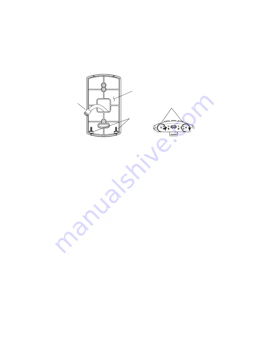
1. Turn the Allen screws in the base of the NetSensor clockwise 

until they clear the cover. Swing the sensor away from the 
mounting base to remove it

2. Route the RJ-12 cable through the mounting base.
3. Fasten the mounting base directly to a 2 x 4 inch outlet box or a 

backplate with the Allen screws toward the floor.

4. Insert the RJ-12 cable coming from the base into the NetSensor.
5. Place the top of the NetSensor over the top of the mounting base 

and swing it down over the Allen screw brackets. Be careful not 
to pinch any wiring.

6. Back the Allen screws out of the brackets until they engage the 

NetSensor cover and hold it in place.

Mounting details

Network 

cable

Allen 

screws

Mounting 

base

Turn clockwise to 

remove from base.

Содержание KMD-1183

Страница 1: ... Guide KMD 1183 1185 NetSensors Contents Specifications 2 Network cable and rough in preparation 5 Installation 6 PC data port 7 Operation 8 Maintainence 8 Programming 9 Important notices 17 Disclaimer 17 903 019 05A Revision A ...

Страница 2: ...ries BACnet controllers BAC 7000 series BACnet controllers Controller Connection Connector type Six wire RJ 12 modular jack Cable type and length Up to 75 feet 22 9 meters maximum conductors no smaller than 24 AWG Power 5 volts DC supplied by connected controller Weight 2 8 ounces 80 grams Material Light almond ABS UL Flame Class 94HB Mounting Surface mount directly to any flat surface or to a 2 x...

Страница 3: ... 7 Temperature sensor Type CMOS Accuracy 0 9 F 0 5 C offset from 40 to 104 F 4 4 to 40 0 C offset is adjusted in the controller Resolution 0 1 F 0 1 C Operating range 36 to 120 F 2 2 to 48 8 C Response time 5 30 seconds Humidity sensor Type CMOS Range 0 100 relative humidity Accuracy at 25 C 2 from 10 90 relative humidity Response time Less than or equal to 4 seconds Environmental limits Operating...

Страница 4: ...KMC Controls 4 Dimensions A B C D E 3 25 in 5 16 in 2 58 in 3 25 in 0 87 in 83 mm 116 mm 66 mm 83 mm 22 mm A C D E B ...

Страница 5: ...s Connectors must be appropriate for the cable in use and are installed following the connector manufacturers instructions Complete rough in wiring at each sensor location prior to sensor installation This includes the following Routing the network cable from the NetSensor to a controller See Mounting details on page 6 If required install the appropriate backplate See Accessories on page 3 for mod...

Страница 6: ...h outlet box or a backplate with the Allen screws toward the floor 4 Insert the RJ 12 cable coming from the base into the NetSensor 5 Place the top of the NetSensor over the top of the mounting base and swing it down over the Allen screw brackets Be careful not to pinch any wiring 6 Back the Allen screws out of the brackets until they engage the NetSensor cover and hold it in place Mounting detail...

Страница 7: ...USB to WinControl or BACstage use a KMD 5576 USB Communicator see the illustration above For EIA 232 to BACstage use a third party interface For EIA 232 to WinControl use a KMD 5559 CommTalk and KMD 5624 cable or equivalent interface To use the PC data port 1 Connect the keyed flat end of the KMD 5624 NetSensor interface cable included with the KMD 5576 but not the KMD 5559 to the port on the NetS...

Страница 8: ... Button 8 comes from simultaneously pressing Buttons 5 and 7 The actual operation of the programmable buttons depends upon the programming in the controller to which the NetSensor is connected See Programming on page 9 The display reverts back to the default room temperature display about ten seconds after the last button press The up and down arrow buttons adjust programmed values where applicabl...

Страница 9: ...NetSensor button numbers for the button numbers Table 3 1 lists typical settings for programming a NetSensor with WinControl Use the NetSensor dialog found under the Control Menu to configure each button Table 3 2 lists typical settings for programming a NetSensor with BACstage Use the NetSensor dialog in the Device Menu to configure each button NetSensor button numbers 2 1 3 4 5 6 7 8 Aux ...

Страница 10: ...ill continue being shown on the NetSensor s display However humidity readings will no longer be read by the controller Note The day of week and system time functions are not enabled in all models of the controllers with which the NetSensor may operate Before programming a controller for one of these features verify the feature is available in the firmware history for the controller For additional ...

Страница 11: ...Read Only Deg F Deg C Analog 2 Cooling Setpoint Analog 0 Decimal Read Write Deg F Deg C Analog 3 Heating Setpoint Analog 0 Decimal Read Write Deg F Deg C Analog 4 Override Digital Off On Read Write Off On Digital 5 System time Analog RTC Time Read Write Time Analog 6 Alarm Digital Off On Read Off On Digital 7 Humidity Analog 0 Decimal Read Write RH Analog 8 Day of Week OR Analog DOW Read Write Unu...

Страница 12: ...e Units 1 Temperature Mode button AV F or C Read Only AV F or C 2 Cooling Setpoint AV 0 Read Write AV F or C 3 Heating Setpoint AV 0 Read Write AV F or C 4 Override BV Off On Read Write BV Off On 5 Time AV Time Read Only AV Hours 5 System time Hours Read Write 6 Alarm BV Off On Read Only BV Off On 7 Humidity AV 0 Read Write AV RH 8 Day of Week OR Day of Week Read Write 8 Auxiliary BV Off On Read W...

Страница 13: ... in WinControl or an analog value object in BACstage The precision of the display is set by Range in WinControl and Display Format in BACstage The typical value is 0 Operators can view and change the setpoint by first touching Button 2 or by pressing the Mode button until the SETPOINT COOLING mode is displayed and then pressing an up or down arrow button Write a Control Basic to control equipment ...

Страница 14: ...e real time clock Use this function only with a stand alone Tier 2 KMD controller or the time master in BACnet MS TP network Operators can view and change the system time by first touching the Button 5 and then pressing an up or down arrow button In WinControl only add a Control Basic line such as the following 40 VAR5 TIME Alarm Pushing Button 6 allows the user to check the status of the defined ...

Страница 15: ...pe to Analog Set Range to DOW Under Description enter the name description or mnemonic of the variable that will store the day of week value Table 3 3 Alarm functions State KMD 1183 KMD 1185 Alarm Displays room temperature When Button 6 is pressed ON is momentarily displayed Displays flashing ALM alternates with room temperature display Pressing Button 6 suppresses ALM indication for 10 minutes an...

Страница 16: ...display the day of week value is represented by 1 through 7 being Sunday through Saturday Verifying a functioning NetSensor To check if a functioning NetSensor is present use the Control Basic function NETSENSOR STATUS 10 IF NOT NETSENSOR STATUS THEN STOP OUT1 Verifying firmware version Simultaneously push Button 2 COOL SP and Button 4 OVERRIDE to display the version of the firmware in the NetSens...

Страница 17: ...thout the written permission of KMC Controls Inc Printed in U S A Disclaimer The material in this manual is for information purposes only The contents and the product it describes are subject to change without notice KMC Controls Inc makes no representations or warranties with respect to this manual In no event shall KMC Controls Inc be liable for any damages direct or incidental arising out of or...

Отзывы: