Page 18 of 32
pipes, then push the start button (Fig. 7).
Caution:
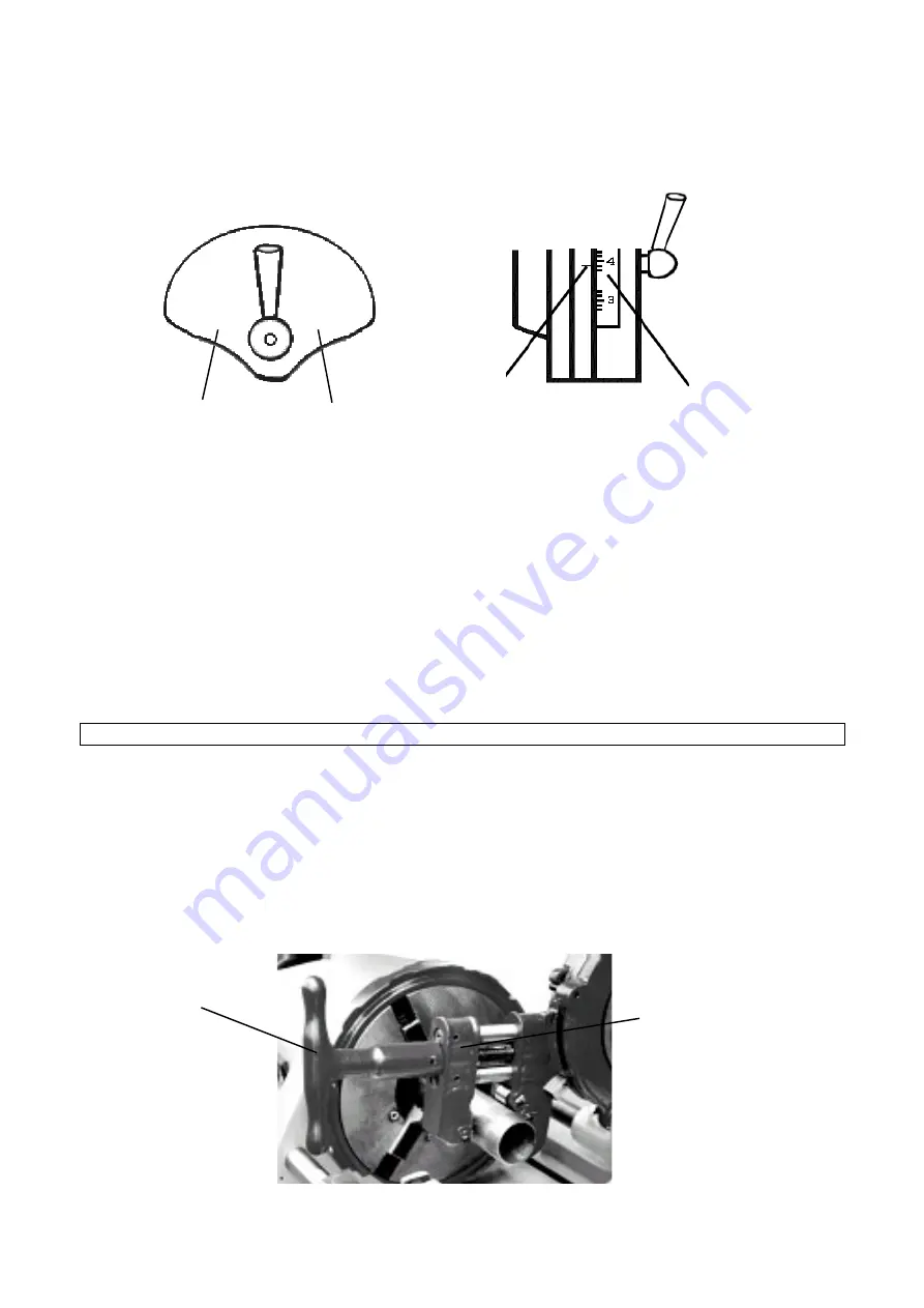
To achieve good pipe threads, the gear shift should be placed at Slow when threading larger pipes
with a diameter bigger than two inches or at Fast for smaller pipes (see Fig. 7).
SLOW FAST
2-1/2"-4" 1/2"-- 2"
Calibration Marks Scale Indicator
Bottom Gear Top Gear
Fig. 7 Fig. 8
5. The pipe must rotate counterclockwise. Then rotate the sledge handle to move the die head to the pipe.
6. Apply force on the sledge handle (Fig. 5) until 3 - 4 threads are cut on the pipe.
7. Stop applying force. The machine will begin to thread automatically until the roller of the die head passes
the copy block and drops.
8. Turn off the threader
9. Move the die head to the up-right unused position.
10. Loosen the fore and rear chucks, by turning them clockwise, and remove the pipe from the rear chuck.
Cutting Pipe
Note:
Any step requiring a non-rotating condition should be done only when the machine is stopped.
1. Turn the fore and rear chucks clockwise. Then loosen the three claws and install the pipe from behind the
rear chuck, passing it through the fore chuck and past it by about 4 inches (100 mm).
2. Holding the pipe, turn the fore and rear chucks counterclockwise to secure the pipe then moderately
tighten the hammer disk by turning it counterclockwise (Fig. 5).
3. Rotate the die head and the beveling rack (reamer; Fig. 10) up out of the way then rotate the knife rack in.
4. Push down the cutting knife rack and rotate the handle to open the rack until the cutting knife roller and
cutting wheel straddle the pipe (Fig. 9).
5. Rotate the sledge handle (fig. 5) to move the cutting knife into position (see Fig. 9).
Cutting Knife Handle
Cutting Knife Rack
Содержание 49671
Страница 21: ...Page 21 of 32 Wiring Diagram...


