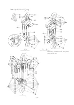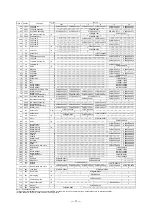
—
18
—
8.2.2 Assembly and adjustment
Assembly procedures
Remarks
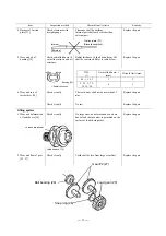
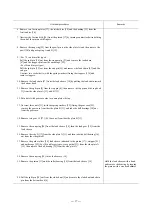
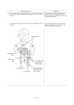
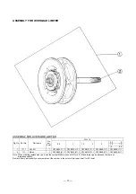
1. Apply grease to the rollers of the roller bearing [18] and insert the pinion
[17] (from the side of the brake screw) into the roller bearing and insert
them together into the load sheave [14]. Fix them with a snap ring [19].
The arrow* direction on the outer side of the
roller bearing shall be faced to pinion gear side.
When inserting, use a screwdriver on the bearing
and tap it with a wooden hammer. Always make
sure that the snap ring is correctly seated.
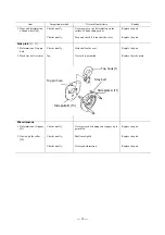
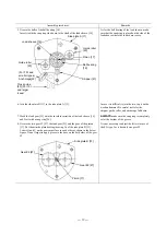
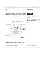
2. Put the side plate A [11] with a brake cover side down and insert the ball
bearing [15] (with a snap ring side up) into the side plate A. Grease the balls
of ball bearing shown in the side plate A.
3. Insert the load sheave [14] with a part of involute serration side (pinion gear
side) up into the ball bearing [15]. The stripper [21] must be put as well.
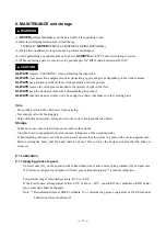
4. <For 7.5t and smaller types>
Put the guide rollers [20] and the anchorage [22] on the side plate A [11].
<For 10t and larger types>
Put the guide rollers [20] and the cross guide [53] on the side plate A [11].
Put the cross guide so that the longer arm fits to
the side plate A.
Load sheave [14]
Pinion [17]
Arrow*
Roller bearing [18]
Snap ring [19]
Side plate A [11]
Pinion [17]
Stripper [21]

