10
7. Press the CLEAN button. See “Using the Controls.” The light
will blink, indicating that the cleaning cycle is in process.
When the indicator light turns green (approximately
70 minutes), the cleaning cycle is complete. During the
cleaning cycle, the system will both clean and rinse itself.
8. After the cleaning cycle is complete, remove the drain cap
from the water pan. Look for any cleaning solution left in the
water pan. If cleaning solution drains from the water pan, you
should run the clean cycle again. Be sure to replace the drain
cap securely on the water pan. If the drain cap is loose, water
will empty from the water pan and you will have either thin ice
or no ice.
NOTE: Severe scale buildup may require repeated cleaning with
a fresh quantity of cleaning solution.
9. Push the selector switch to ON to resume ice production.
Condenser
A dirty or clogged condenser:
■
Obstructs proper airflow.
■
Reduces ice making capacity.
■
Causes higher than recommended operating temperatures
which may lead to component failure.
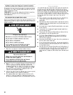
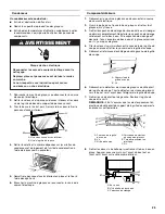
1. Unplug ice maker or disconnect power.
2. Remove the two screws in the lower access panel and the
two screws from the base grille area of the front panel
support.
3. Pull the bottom forward and then pull down to remove the
lower access panel.
4. Remove dirt and lint from the condenser fins and the unit
compartment with a brush attachment on a vacuum cleaner.
5. Replace the lower access panel using the four screws.
6. Plug in ice maker or reconnect power.
Interior Components
1. Unplug ice maker or disconnect power.
2. Open the storage bin door and remove any ice that is in the
bin.
3. Remove the drain cap from the water pan and drain
thoroughly. Replace the drain cap securely on the water pan.
If the drain cap is loose, water will empty from the water pan,
and you will have either thin ice or no ice.
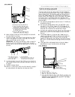
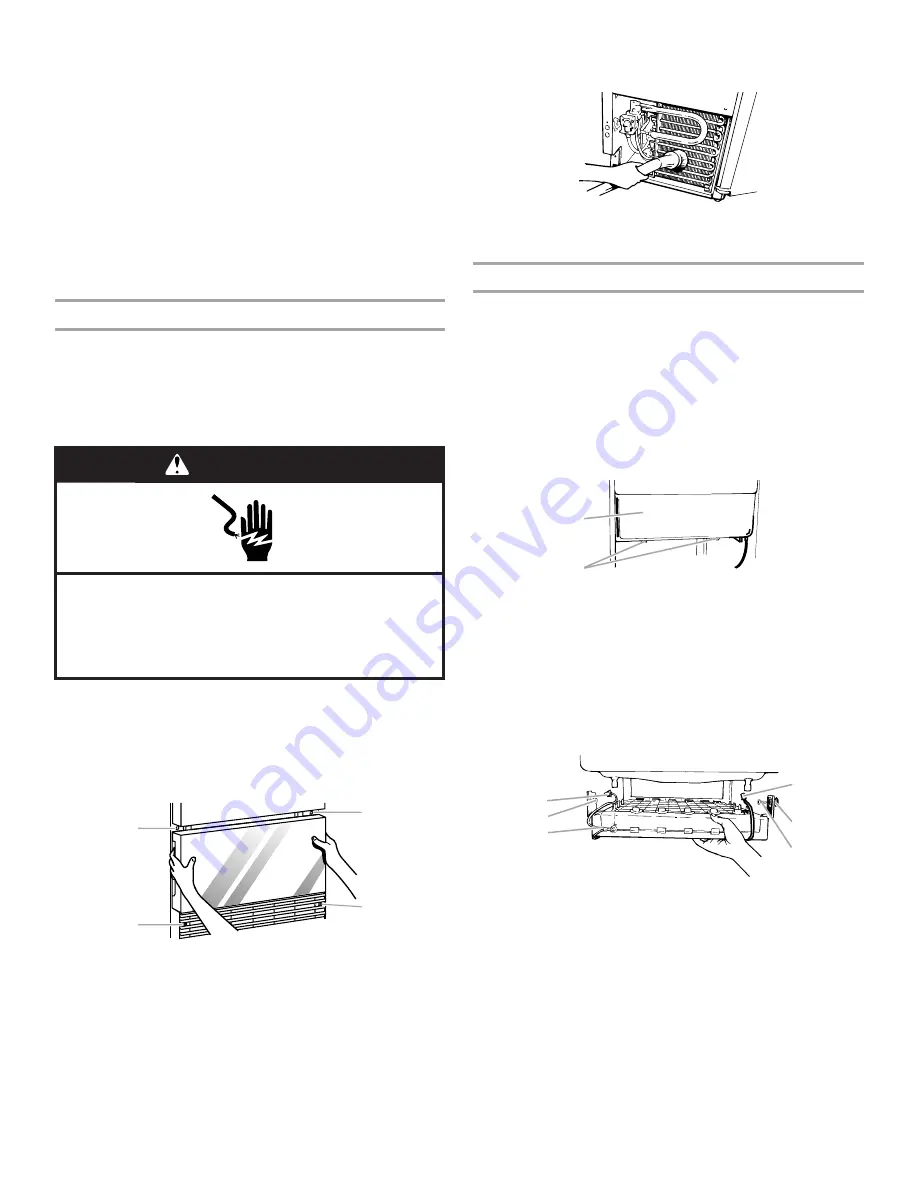
4. Remove the two screws that hold the cutter grid cover in
place and remove the cutter grid cover.
5. Unplug the wiring harness from the left side of the cutter grid.
6. Unplug the ice level sensor from the right side of the cutter
grid. Pull the ice level sensor down and forward away from
the cutter grid.
7. Remove the right-hand and left-hand screws. Lift the cutter
grid up and out.
NOTE: Make sure the plastic spacer from the right-hand side
of the cutter grid bracket stays with the cutter grid.
A. Lower access panel screws
B. Base grille screws
WARNING
Electrical Shock Hazard
Disconnect power before cleaning.
Replace all parts and panels before operating.
Failure to do so can result in death or electrical shock.
A
B
A
B
A. Cutter grid cover
B. Screws
A. Cutter grid harness
B. Screw
C. Cutter grid
D. Ice level sensor harness
E. Plastic spacer
F. Screw
A
B
A
B
C
D
E
F
Содержание KUIC18PNTS
Страница 16: ...16 Notes ...


