6
English
Setting up your Stand Mixer
Assembling your Bowl-Lift Stand Mixer
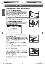
To attach the Stainless Steel Bowl
Turn speed control to “0” (OFF). Unplug Stand Mixer or disconnect
power. Place Bowl Lift Lever into down position. Fit Bowl Supports
over Locating Pins and press down on back of the bowl until the
Bowl Pin snaps into the Spring Latch. (Fig. 1)
IMPORTANT:
If the bowl is not securely snapped into place, it will
be unstable and wobble during use.
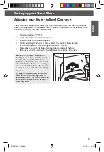
To raise the Stainless Steel Bowl to mixing position
Rotate Bowl Lift Lever counterclockwise to the straight up position. (Fig. 2)
The bowl must always be in the raised position when mixing.
To remove the Stainless Steel Bowl
Turn speed control to “0” (OFF). Unplug Stand Mixer or disconnect
power. Place Bowl Lift Lever in down position. Grasp Bowl Handle
and lift straight up and off Locating Pins.
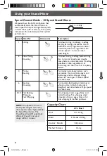
To attach Flat Beater, Stainless Steel Whip,
or Spiral Dough Hook.
Turn speed control to “0” (OFF). Unplug Stand Mixer or disconnect
power. Lower bowl by rotating Bowl Lift Lever downward. Slip beater
on Beater Shaft and press upward as far as possible. Turn beater to right,
hooking it over the Pin on the Beater Shaft.
(Fig.3)
To remove Flat Beater, Stainless Steel Whip
or Spiral Dough Hook
Turn speed control to “0” (OFF). Unplug Stand Mixer or disconnect
power. Lower bowl by rotating Bowl Lift Lever downward. Press beater
upward as far as possible and turn left. Pull beater from Beater Shaft.
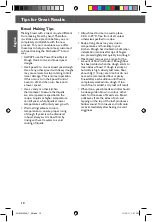
To attach Pouring Shield
Turn speed control to “0” (OFF). Unplug Stand Mixer or disconnect
power. Attach Flat Beater, Spiral Dough Hook, or Stainless Steel Whip
and bowl. From the front of the mixer, slide the Pouring Shield over
the bowl until the it is centered. The bottom rim of the Pouring Shield
should fit within the bowl. (Fig. 4)
To use Pouring Shield
For best results, rotate the Pouring Shield so the Motor Head covers
the U-shaped gap in the shield. The Pouring Chute will be just to the right
of the Attachment Hub as you face the mixer. Pour the ingredients into
the bowl through the Pouring Chute.
Fig. 1
Locating Pin
Spring Latch
Pin
Fig. 2
Fig. 3
Fig. 4
Pouring
Chute
W10421400A_1_EN.indd 6
11/15/11 1:47 PM


