10
Assembly
The SHE control panel has to be installed in a dry room. The
assembly places for the SHE manual call points and the vent
switches must be well visible and accessible (SHE call point =
1.4 m over the top edge of the floor). Do not assemble behind wall
projections, door casements or hide behind construction elements.
Open the SHE control panel and fix it at the specified bore-holes to
the construction body. Make sure to provide appropriate material
for the fixations. Assembly of control elements, drives, junction
boxes (max.1.2 m to the drive) and automatic detectors according
to their joint operating instructions. Please observe applicable
regulations and safy instruction (see page 4+5).
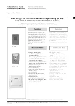
SHE manual call point TRZ/RBH-Basic
SHE manual call point, integrated in the TRZ Plus front door.
Installation
Disconnect power supply (mains and battery), mount additional
module at the inside of the control panel door, plug the plug to the
extension ledge of the principal circuit control board or, if available,
of the add. module TRZ/WRMAS, reconnect power supply (mains
and battery).
Function check
Procede as indicated page 27, point “SHE man. call point“, repeat
the complete bringing into service of the TRZ Plus, no errors,
function OK, system is ready for operation.
Montage
Die Montage der Steuerzentrale muss in trockenem Raum erfolgen.
Die Montageorte der RWA-Bedienstellen und Lüftungstaster
müssen gut sichtbar und erreichbar sein (RWA-Bedienstelle =
1,4 m über Fußbodenoberkante). Nicht hinter Wandvorsprüngen,
Türflügeln oder von Baukörpern verdeckt montieren.
Steuerzentrale öffnen und an den vorgegebenen Bohrungen am
Baukörper befestigen. Für geeignetes Befestigungsmaterial ist zu
sorgen. Bedienelemente, Antriebe, Anschlussdosen (max. 1,2 m
zum Antrieb) und automatische Melder nach deren beiliegenden
Bedienungsanleitungen montieren. Entsprechende Vorschriften
und Sicherheitshinweise (siehe Seite 4+5) einhalten.
Additional modules connection
Anschlüsse Zusatzmodul
RWA-Bedienstelle TRZ/RBH-Basic
zum Einbau in die Fronttür der TRZ-Plus
Einbau
Zentrale stromlos schalten (Netz und Akku), Zusatzmodul auf der
Innenseite der Zentralentür montieren, Stecker auf die
Erweiterungsleiste der Grundplatine oder - wenn vorhanden - auf
die Erweiterungsleiste des Zusatzmoduls TRZ/WRMAS stecken,
Stromversorgung wieder herstellen (Netz und Akku).
Funktion RWA-Bedienstelle prüfen
Gemäß Seite 27 Punkt “RWA-Bedienstellen” verfahren, komplette
Inbetriebnahme der TRZ Plus wiederholen, keine Fehler,
Funktion ist in Ordnung, die Anlage ist betriebsbereit.
Taste
RW-Auslösung
SHE-activation
Switch
RWA Bedienstelle TRZ/RBH
SHE manual call point TRZ/RBH
OK
!
LED-Anzeigen
LED display
Erweiterungsleiste
Extension ledge
Taste
RWA-ZU (kein Reset)
SHE-Close (no reset)
Switch


