background image

ADJUSTMENTS & OPERATION

Blade Selection

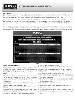
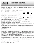
This bandsaw is equipped with a saw blade that is adequate for a variety of jobs on a variety of common materials. Refer to Fig. 8 below for

the speeds recommended for various materials. These speeds, while appropriate for many common cutting needs, do not encompass the

wide variety of special blade configurations (tooth pitch and set) and special alloys for cutting unusual or exotic materials.

A coarse blade could be used for a solid steel bar, but a finer tooth blade would be used on a thin-wall steel tube. In general, the blade choice

is determined by the thickness of the material; the thinner the materials, the finer the tooth pitch. A minimum of three teeth should be on the

work piece at all times for proper cutting. The blade and workpiece can be damaged if the teeth are so far apart that they straddle the work

piece.

For very high production cutting of special materials, or to hard-to-cut materials such as stainless steel, tool steel or titanium, you can ask

your industrial distributor for more specific blade recommendations. The supplier that provides the workpiece material should be able to 

provide you with very specific instructions regarding the best blade (and coolant or cutting fluid, if needed) for the material or shape supplied. 

Blade Removal and Installation

Warning!

Use leather gloves when changing the saw blade to protect

your hands from cuts and scratches. Use protective eye wear that

meets ANSI specifications.

Warning! Disconnect the bandsaw from its electrical power

source.

1) To remove the blade, place the saw frame in the rearmost position

by pushing down on the saw frame release lever (H-Fig.6) and lock

it by turning the hydraulic feed stop dial (E-Fig.6) clockwise.

2) Remove the cabinet side panel (diagram# 173) to expose the lower

blade wheel.

3) Open the upper wheel cover (diagram# 124) to expose the upper

blade wheel.

4) Remove the blade safety guard (diagram# 41) .

5) Turn the blade tension handle (A-Fig.6) counterclockwise until the

blade hangs loose.

6) Use leather gloves to prevent cuts and scratches. Pull the blade off

the drive wheels and out of the blade guides. Store the removed

blade carefully before proceeding.

7) To install the blade, slide the new blade into the blade guides.

8) Place the blade over the bottom wheel.

9) Place the blade over the top wheel. The teeth must point down

toward the table.

10) Push the blade so it is seated against the shoulders of the wheels.

11) Turn the blade tension handle clockwise enough to hold the blade

firmly in place.

12) Reconnect the saw to its electrical power source.

13) Turn the machine on to allow the blade to position itself. Check and

adjust the tracking of the blade. Refer to Blade Tracking

Adjustments in this manual.

14) Turn the blade tension handle clockwise to finish tightening the

blade. Do not over-tighten the blade; tighten it just enough so it

does not slip while cutting.

15) Reinstall the wheel guards and blade covers.

The most common causes of your bandsaw not cutting straight are:

1) Blade tension is set too low.

2) The blade is either dull or worn on one side. Blade teeth may have

lost their set.

3) The blade is upside down. The teeth must point down toward the

table.

FIGURE 8

Содержание KC-914H

Страница 1: ...INSTRUCTION MANUAL MODEL KC 914H 14 SELF FEED VERTICAL METAL CUTTING BANDSAW COPYRIGHT 2004 ALL RIGHTS RESERVED BY KING CANADA TOOLS INC ...

Страница 2: ...mer a 1 year limited warranty as of the date the product was purchased at retail and that each product is free from defects in materials Warranty does not apply to defects due directly or indirectly to misuse abuse negligence or accidents repairs or alterations and lack of maintenance KING CANADA shall in no event be liable for death injuries to persons or property or for incidental special or con...

Страница 3: ...uttered areas and benches invite accidents Make sure the floor is clean and not slippery due to wax and sawdust build up 6 AVOID DANGEROUS ENVIRONMENT Don t use power tools in damp or wet locations or expose them to rain Keep work area well lit and provide adequate surrounding work space 7 KEEP CHILDREN AWAY All visitors should be kept a safe distance from work area 8 MAKE WORKSHOP CHILD PROOF Use...

Страница 4: ...T USE A TWO PRONG ADAPTOR FOR THEY ARE NOT IN ACCORDANCE WITH LOCAL CODES AND ORDINANCES NEVER USE IN CANADA 220V OPERATION If 220V single phase operation is desired the following instructions must be followed 1 Disconnect the machine from its power source 2 The bandsaw comes with four motor leads that are connected for 110V operation Reconnect these four motor leads for 220V operation as indicate...

Страница 5: ...WxH 45 x 33 x 68 Prewired 110V MODEL KC 914H Height under guides 14 Throat capacity 8 1 2 Blade width min max 1 8 1 Blade length 120 Table size 18 1 2 x 30 1 2 Table height from floor 30 Voltage 110V 220V 1 phase 60 Hz Weight 550 LBS 110V Wiring Diagram 220V Wiring Diagram KC 914H Specifications FIGURE 4 FIGURE 5 ...

Страница 6: ...e machine on an uneven floor J Depth Stop Knob Locks the depth stop in position K Depth Stop Allows cuts at a predetermined depth L Upper Blade Wheel Blade Tracking Adjustment See Blade Tracking Adjustments If your saw should get out of adjustment and the blade runs off the wheel or runs back against the lip loosen the two bottom cap screws on the upper wheel sliding bracket Turn the set screw in ...

Страница 7: ... Controls On Off Switch G Fig 6 Located on the right side of the control panel Press this switch to start or stop the machine Hydraulic Feed Rate Control F Fig 6 Located on the bottom left side of the control panel This dial is the hydraulic cylinder feed control valve It is used to set the amount of force that is applied to the saw blade in combination with the couterbalance force The feed rate i...

Страница 8: ... bandsaw from its electrical power source 1 To remove the blade place the saw frame in the rearmost position by pushing down on the saw frame release lever H Fig 6 and lock it by turning the hydraulic feed stop dial E Fig 6 clockwise 2 Remove the cabinet side panel diagram 173 to expose the lower blade wheel 3 Open the upper wheel cover diagram 124 to expose the upper blade wheel 4 Remove the blad...

Страница 9: ...he feed rate and applies more force to the saw blade and the workpiece The needle valve is adjusted until the bandsaw is operating efficiently The efficiency of operation is usually evaluated by observing chip formation Refer to Evaluating Cutting Efficiency for more information on cutting efficiency Evaluating Cutting Efficiency Is the blade cutting efficiently The best way to determine this is t...

Страница 10: ... insufficient adjust the counterweight diagram 191 position to adjust the amount of force the saw puts on the workpiece 11 Turn the lock knob on the counterweight counterclockwise to loosen it slide counterweight into new position and retighten lock knob 12 At the end of the cut push down on the saw frame release lever to move the saw frame back to the rearmost position and turn the hydraulic feed...

Страница 11: ...e clearance by approximately 0 001 4 Retighten the blade guide set screws with the hex key 5 Use the same procedure to adjust the other blade guide bearing 6 When the adjustment is correct the guide bearings should rotate freely with slight pressure of the finger blade stopped Cleaning 1 Clean off any oil and grease on the machine surfaces 2 After cleaning coat the machined surfaces of the bandsaw...

Страница 12: ...rd spots in the workpiece 5 Scale on in the workpiece 6 Work hardening of material especially stainless steel 7 Insufficient blade tension 8 Operating the saw without pressure on the workpiece 1 Blade is binding in the cut 2 Blade tension is too high 1 Blade guides are worn 2 Blade guide bearings are not adjusted 3 Blade guide bearing bracket is loose 1 Work piece is not square with the blade 2 Fe...

Отзывы: