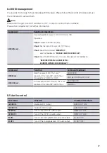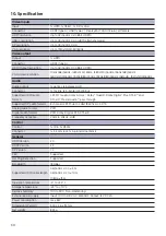
23
6.3 EDID settings
The EDID (Extended Display Identifi cation Data) is typically used by the source device to match its video
resolution with the connected display. In some circumstances it is helpful to set the EDID to a fi xed value.
The
MultiSwitch 41 4K60
supports an advanced EDID management including an extensive list of
predefi ned EDID settings, please check the table below for further details.
Use the 4-pin DIP switch
9
on the rear panel to set the EDID to a predefi ned value.
Note:
• Stereo Audio: LPCM 2Ch
• High Defi nition Audio: LPCM 8Ch, AC-3 6Ch, DTS 5.1, Dolby Digital 5.1
• The four user-defi ned EDID can be customized by RS232 command,
please refer to
chapter 8.4 EDID management
for more details.
Switch status
Video
Audio
Switch in the
lower position
= „ON“,
Swich in the upper
position
= „OFF“
0000
Pass through (Default)
Pass through (Default)
0001
1920x1080@60Hz RGB 4:4:4 8bit
Stereo
0010
1920x1080@60Hz RGB 4:4:4 8bit
High Defi nition
0011
1920x1080@60Hz RGB 4:4:4 12bit
Stereo
0100
1920x1080@60Hz RGB 4:4:4 12bit
High Defi nition
0101
3840x2160@60Hz RGB 4:2:0 12bit
Stereo
0110
3840x2160@60Hz RGB 4:2:0 12bit
High Defi nition
0111
3840x2160p@60Hz 4:4:4 HDR 12bit
Stereo
1000
3840x2160p@60Hz 4:4:4 HDR 12bit
High Defi nition
1001
1280x800@60Hz RGB 4:4:4 8bit
Stereo
1010
1920x1200@60Hz RGB 4:4:4 8bit
Stereo
1011
User-defi ned EDID 1.
1100
User-defi ned EDID 2.
1101
User-defi ned EDID 3.
1110
User-defi ned EDID 4.
1111
Enable RS232 EDID management.
HDMI V2.0 4x1 Presentation Switcher with Audio Extraction
7
5.4 VGA Resolution Selection
The
RES
button on the front panel is designed for VGA resolution selection.
When switch to VGA input, press
RES button repeatedly to set the output resolution to
1280x720, 1920x1080 or 1920x1200, and its corresponding LED will illuminate green.
5.5 EDID Setting
The Extended Display Identification Data (EDID) is used for the source device to match
its video resolution with the connected display. The 4-pin DIP switch on the rear panel
can be used to set the EDID to a built-in fixed value. Use the following table to determine
the setting for the 4-pin DIP switch for specific video resolution and audio capabilities.
The switch represents “0” when in the lower (
OFF
) position, and it represents “1” while
putting the switch in the upper (
ON
) position.
Switch Status
EDID
0000
EDID pass-through (Default)
0001
1920x1080@60Hz RGB 4:4:4 8bit Stereo Audio
0010
1920x1080@60Hz RGB 4:4:4 8bit High Definition Audio
0011
1920x1080@60Hz RGB 4:4:4 12bit Stereo Audio
0100
1920x1080@60Hz RGB 4:4:4 12bit High Definition Audio
0101
3840x2160@60Hz RGB 4:2:0 12bit Stereo Audio
0110
3840x2160@60Hz RGB 4:2:0 12bit High Definition Audio
0111
3840x2160p@60Hz 4:4:4 HDR 12bit Stereo Audio
1000
3840x2160p@60Hz 4:4:4 HDR 12bit High Definition Audio
1001
1280x800@60Hz RGB 4:4:4 8bit Stereo Audio
1010
1920x1200@60Hz RGB 4:4:4 8bit Stereo Audio
1011
User-defined EDID 1.
1100
User-defined EDID 2.
1101
User-defined EDID 3.
1110
User-defined EDID 4.
1111
Enable RS232 EDID management.
Note:
l
Stereo Audio: LPCM 2Ch.
l
High Definition Audio: LPCM 8Ch, AC-3 6Ch, DTS 5.1, Dolby Digital 5.1.
l
The four user-defined EDID can be customized by RS232 command, please refer to
7.2.4 EDID management for more details.

