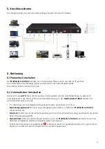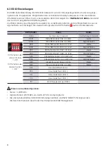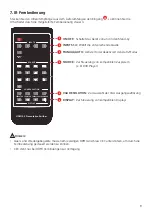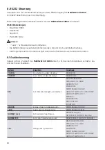
21
4.2 Rear panel
1
HDMI IN:
Type A HDMI input
2
USB-C IN:
USB type C input to connect sources supporting HDMI alt mode via USB-C
3
DP IN:
DisplayPort input
4
VGA IN:
VGA video input
5
VGA Audio IN:
Analogue stereo audio input, related for VGA input
6
HDMI OUT:
Type A HDMI output to connect e. g. to projector or display
7
OPTICAL:
Digital audio output
8
L/R:
Analogue, balannced audio output
9
EDID:
4-pin DIP switch for EDID settings
10
IR IN:
3,5 mm jack socket to connect IR receiver, to control it by supplied IR remote
11
RS232:
To remote control switcher via RS232 commands
12
DC 12V:
Hollow plug socket to connect the supplied power supply unit
HDMI V2.0 4x1 Presentation Switcher with Audio Extraction
5
3.2 Rear Panel
①
1. HDMI IN:
Connects to HDMI video source.
②
2. USB-C IN:
Connects to the video source with SlimPort output, e.g. Macbook.
③
3. DP IN:
Connects to DisplayPort video source.
④
4. VGA IN:
Connects to VGA video source.
⑤
VGA Audio IN:
Connects to audio source to be embedded in VGA video.
⑥
HDMI OUT:
Connects to HDMI display device.
⑦
OPTICAL:
Connects to audio playback device.
⑧
L/R (5-pin balanced audio):
Connects to audio playback device.
⑨
EDID:
4-pin DIP switch for EDID setting.
⑩
IR IN:
Connects to IR receiver to control the switcher by IR remote.
⑪
RS232:
Connects to RS232 control device (e.g. PC) to control the switcher by
RS232 commands.
⑫
DC 12V:
DC barrel port for power adapter connection.
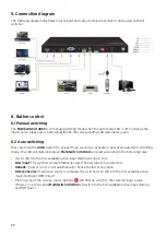
4. System Connection
The following diagram illustrates typical input and output connections that can be
utilized with this switcher:
1. HDMI IN
4. VGA IN
2. USB-C IN
HDMI OUT
OPTICAL
Tx
Rx
RS232
IR IN
EDID
ON
OFF
1
0
L
R
1 2 3 4
3. DP IN
1
2
3
4
5
6
7
8
9
1
2
3
4
5
6
7
8
9
10
11
12

