


HIGH PRESSURE CONTROL VALVE
Installation, Operation & Maintenance Guide
7
www.kimray.com
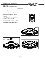
Model: PO, PC
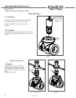
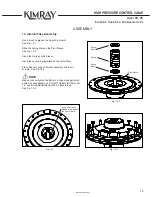
1 Installation
Before installing the control valve, inspect it for shipment
damage and for foreign material that may have collected during
shipment. Inspect the openings in the valve and clean the pipe
lines to remove scale, chips and debris.
1. Install the valve with the arrow on the body pointing in the
direction of flow. The arrow indicates that the direction of flow
and will not necessarily prevent flow in the opposite direction.
The flow direction of the HPCV PB is up through
the valve. The stem guided trim is down through
the valve. If conditions indicate the possibility of
back word flow, you may wish to install check valves.
2. Install the valve using good piping practice. For flanged
bodies use a suitable gasket between the body and the pipeline
flanges. For threaded (NPT) bodies, use TFE Tape or pipe
thread sealant on external pipe threads.
3. Connect instrument gas to the actuator connection. The
maximum required instrument gas pressure is 30 psig (2 bar);
45 psig (3 bar) is permissible.
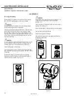
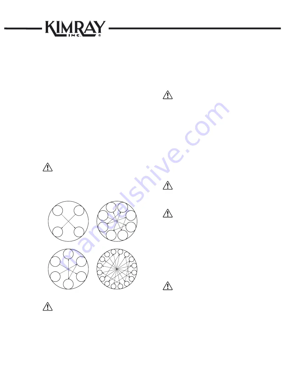
NOTE:
Always check fastener tightness prior to valve installation,
testing, and use, as fasteners have the potential to loosen
in transit. This is recommended to ensure your safety and
proper valve function.
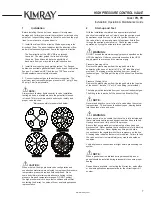
*Kimray assembly torque method below*
Four Bolt
Four Bolt
11
22
33
44
Six Bolt
Six Bolt
11
22
33
44
55
66
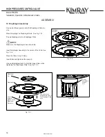
Eight Bolt
Eight Bolt
11
22
33
44
55
88
66
77
Sixteen Bolt
Sixteen Bolt
11
22
99
14
14
55
16
16
88
11
11
44
13
13
10
10
66
15
15
77
12
12
33
CAUTION:
When ordered, the high pressure valve configuration and
construction materials were selected to meet specific pressure,
temperature, pressure drop and fluid conditions. Since
some body/trim material combinations are limited in their
pressure drop and temperature ranges, DO NOT subject
the high pressure valve to any other conditions without first
contacting the Kimray Inc, sales office or a sales/applications
representative.
2
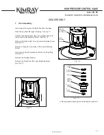
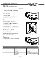
Start-up and Test
With the installation completed and appropriate relief and
check valves installed and set, slowly open the upstream and
downstream shutoff valves. In order to test the function of
the valve, allow only a small amount of upstream fluid to flow
through the upstream shutoff valve. Check for proper valve
operation by cycling the actuator arm several times.
WARNING:
DO NOT exceed the maximum supply pressure specified on the
HPCV nameplate. Under no circumstances should the HPCV
supply pressure ever exceed the maximum psig.
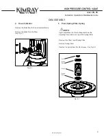
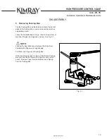
Pressure Opening Valve
Remove the plastic stopper from the tapped hole in the
underside of the bonnet. Install a 1/4” or 3/8” tube fitting (not
provided). The tubing must be installed from your source of
instrument gas. The fitting at the top of the bonnet is a Breather
Plug.
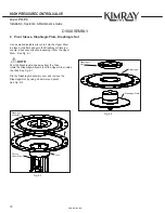
Pressure Closing Valve
Remove the plastic stopper from the tapped hole in the top side
of the bonnet. Install a 1/4” or 3/8” tube fitting (not provided).
The tubing must be installed from your source of instrument gas.
The fitting in the lower half of the bonnet is a Breather Plug.
NOTE:
Never stand directly over or in front of a valve when the system
is pressurized. The valve could suddenly open, blowing debris
into the person’s face and eyes.
WARNING:
Before any service, be certain that the valve is fully isolated and
that all pressure upstream and downstream has been relieved.
Use bypass valves or fully shut off the process.
Be sure that any operating or instrument gas lines has been
disconnected. Never assume that a check valve is fully blocking
the downstream line. Never tighten any fitting or the main
connections to the regulator while there is pressure on the line.
A leaking valve indicates that service is required. Failure to take
the valve out of service immediately may create a hazardous
condition.
Verify all pressure connections are tight before pressurizing the
system.
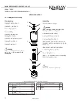
NOTE:
When a gasket seat is disturbed during disassembly a new
gasket should be installed during re-assembly to ensure proper
sealing.
Repair kits are available. contacting the Kimray Inc, sales office
or a sales/applications representative for the correct repair kit
number.