


25
Electricalinstallation
Type 8615500120-000 / 8615500130-000
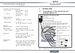
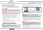
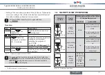
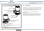
11.3 electrical installation with cable
gland
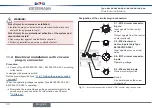
procedure:
→
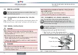
Loosen the 4 screws of the connection cover and remove the
cover. The connection terminals are now accessible.
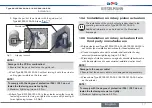
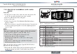
→
Push the cables through the cable gland.
→
Connect the wires.
→
Tighten the union nut of the cable gland (tightening torque
approx. 1.5 Nm).
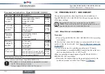
→
Place the connection cover with inserted seal onto the electrical
connection housing and tighten cross-wise (tightening torque
max. 0.7 Nm).
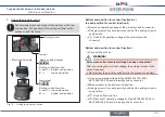
note!
damage or malfunction due to ingress of dirt and moisture!
To comply with the degree of protection IP65 / IP 67:
▶
Close all unused cable glands with dummy plugs.
▶
Tighten the union nut of the cable gland.
Tightening torque depends on cable size or dummy plug
approx. 1.5 Nm.
▶
Only screw on connection cover with the seal inserted.
Tightening torque max. 0.7 Nm.
When the operating voltage is applied, Type 8615500120-000 /
8615500130-000 is operating.
→
Now make the required basic settings and adjustments for the
positioner/process controller. For description see Chapter
"13 Start-up".
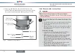
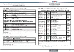
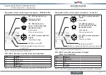
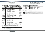
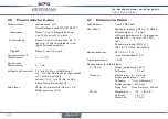
Connection terminals
Switch
10
12
13
14
11
8
9
1
2
3
4
5
6
7
Connection cover
Fig. 14: Cable gland connection
terminal assignment
11
Set-point value +
(0/4 ... 20 mA / 0 ... 5/10 V)
10
Set-point value GND
14
Operating v
24 V DC
13
Operating voltage
GND
12
Binary input +
13
Binary input GND
optional
9
Analog position fe
8
Analog position feedback GND
5
Binary output 1
6
Binary output GND
7
Binary output 2
Tab. 6: Cable gland connection
English
Содержание 8615500120-000
Страница 93: ......
Страница 94: ...www kieselmann de...


