


22
Electricalinstallation
Type 8615500120-000 / 8615500130-000
***
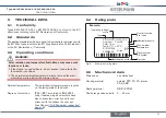
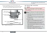
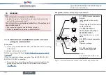
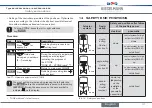
For reasons of wire resistance compensation, connect
the Pt 100 sensor via 3 wires.
Always bridge Pin 3 and Pin 4 on the sensor.
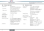
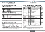
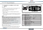
X4 - m8 socket, 4-pole (proximity switch) -
option only
pin
Wire color
*
assignment
1
brown
proximity switch 1 out
2
white
GND
3
blue
24 V DC
The indicated colors refer to the connection cable available as an
accessory.
Tab. 5: X4 ‑ M8 socket, 4‑pole (proximity switch)
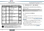
11.2.1 setting the proximity switch - optional
Danger!
risk of injury due to electrical shock!
▶
Before reaching into the system, switch off the power supply
and secure to prevent reactivation!
▶
Observe applicable accident prevention and safety regulations
for electrical equipment!
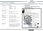
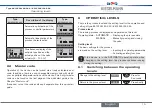
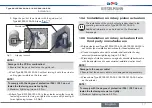
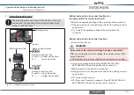
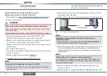
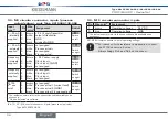
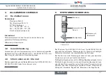
1. Removing housing jacket and electronics module:
→
Disconnect operating voltage at Type 8615500120-000 /
8615500130-000 and proximity switch connector.
note!
Breakage of the pneumatic connection pieces due to rota-
tional impact!
▶
When unscrewing the housing jacket,
do not hold the actuator
but the electrical connection housing above.
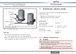
→
Hold the electrical connection housing in place.
→
Unscrew the housing jacket in a counter-clockwise direction and
remove.
→
Remove electronics module.
Housing jacket
Electrical connection
housing
Electronics module
Fig. 11: Removing housing jacket and electronics module.
English
Содержание 8615500120-000
Страница 93: ......
Страница 94: ...www kieselmann de...


