


78
In the Hummer-Bot car, the integrated infrared receiving head has three pins, including the power
supply pin, grounding and signal output pin. The circuit is shown in Fig.3.2.35. Ceramic capacitors is a
decoupling capacitor which can filter the output signal interference. The 1 end is the output of the
demodulation signal which is directly connected to the number 12 port on the Arduino. When the infrared
coded signal is transmitted, it will be processed by the infrared joint, then outputs the square wave signal,
and directly supplied to the Arduino, and the corresponding operation is carried out to control the motor.
Figure .3.2.35 Circuit Diagram and Physical Map of Infrared Receiving Head
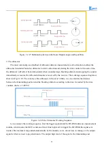
3.2.5.2 Working Principle
The remote control system in general composed of the remote controller (transmitter), and receiver,
when you press any button on the remote control, it will generate the corresponding encoding pulse and
output various control pulse signals based on the infrared, infrared monitor diode sends the signal to the the
amplifier and the pulse amplitude limiter, the limiter controls the pulse amplitude at a certain level,
regardless of the distance of infrared transmitter and receiver. AC signal enters the band-pass filter which
can pass the 30KHZ to the load wave 60KHZ and enters the comparator through the demodulation circuit.
The comparator outputs high or low level and restores the output signal waveform. The system procedure
diagram is shown in Fig.3.2.36.
Содержание Hummer-Bot-1.0
Страница 1: ...Hummer Bot 1 0 Instruction Manual V 2 0 ...
Страница 18: ...15 Step4 You need to install motors Figure 3 1 5 Schematic diagram of motor installation ...
Страница 50: ...47 Figure 3 2 15 Diagram of Data without Obstacles ...
Страница 83: ...80 Test code Path hummer bot Lesson ModuleDemo IrkeyPressed IrkeyPressed ino ...


