background image

Features and Functions

2

Keysight U1241AN User’s and Service Guide

43

Alerts and Warning During Measurement 

Overload Alert

The multimeter provides an overload alert for voltage measurement in both auto 

and manual range modes. The multimeter beeps periodically once the measuring 

voltage exceeds 1100.0 V. 

Input-A Warning Alert 

The multimeter sounds an alerting beep when the test lead is inserted to the 

A


input terminal but the rotary switch is not set to the corresponding 

A

 location. The 

display indicates a flashing 

AErr

 annunciator until the test lead is removed from 

the 

A

 input terminal.

Input-mA Warning Alert 

The multimeter sounds an alerting beep when the 

μ

A/mA

 input terminal detects a 

voltage level of more than 1.6 V. The display indicates a flashing 

CErr

 annunciator 

until the test lead is removed from the 

μ

A/mA

 input terminal.

WARNING

For your safety, please be aware of the overload alert. When you are alerted, 
immediately remove the test leads from the measuring source.

Содержание U1241AN

Страница 1: ...Keysight U1241AN Handheld Digital Multimeter User s and Service Guide ...

Страница 2: ...rights customarily provided to the public to use modify reproduce release perform display or disclose commercial computer software or commercial computer software documentation No additional government requirements beyond those set forth in the EULA shall apply except to the extent that those terms rights or licenses are explicitly required from all providers of commercial computer software pursua...

Страница 3: ...of electric shock Three phase alternating current Caution risk of danger refer to this manual for specific Warning or Caution information Earth ground terminal Caution hot surface Protective conductor terminal Out position of a bi stable push control Frame or chassis terminal In position of a bi stable push control Equipotentiality CAT III 1000 V Category III 1000 V overvoltage protection Equipmen...

Страница 4: ...rated voltage as marked on the multimeter between terminals or between terminal and earth ground Double check the multimeter operation by measuring a known voltage For current measurement power off circuit power before connecting the multimeter to the circuit Always place the multimeter in series with the circuit When connecting probes always connect the common test probe first When disconnecting ...

Страница 5: ... or first aid is present Do not substitute parts or modify equipment to avoid the danger of introducing additional hazards Return the product to Keysight Sales Office for service and repair to ensure the safety features are maintained Do not operate damaged equipment as the safety protection features built into this product may have been impaired either through physical damage excessive moisture o...

Страница 6: ...es are measurements on household appliances portable tools and similar equipment Measurement CAT III Measurements performed in the building installation Examples are measurements on distribution boards circuit breakers wiring including cables bus bars junction boxes switches socket outlets in the fixed installation and equipment for industrial use and some other equipment including stationary moto...

Страница 7: ...mperature up to 30 C decreasing linearly to 50 RH at 55 C Storage environment 40 C to 70 C Altitude Up to 2000 meters per IEC 61010 1 2nd Edition CAT III 1000 V IEC 61010 1 2nd Edition CAT IV 600 V Pollution degree Pollution Degree 2 CAUTION The Keysight U1241AN complies with the following safety and EMC requirements IEC 61010 1 2001 EN61010 1 2001 USA ANSI UL61010 1 2004 Canada CAN CSA C22 2 No 6...

Страница 8: ...is ISM device complies with the Canadian ICES 001 Cet appareil ISM est conforme a la norme NMB 001 du Canada The RCM mark is a registered trademark of the Spectrum Management Agency of Australia This signifies compliance with the Australia EMC Framework regulations under the terms of the Radio Communication Act of 1992 This instrument complies with the WEEE Directive 2002 96 EC marking requirement...

Страница 9: ...a Monitoring and Control Instrument product The affixed product label is as shown below Do not dispose in domestic household waste To return this unwanted instrument contact your nearest Keysight Service Center or visit http about keysight com en companyinfo environment takeback shtml for more information Sales and Technical Support To contact Keysight for sales and technical support refer to the ...

Страница 10: ...ervice and Maintenance This chapter provides you with warranty services maintenance procedures and troubleshooting hints to solve general problems that you may encounter with the instrument Repair or service which are not covered in this manual should only be performed by qualified service personnel Please return to Keysight for product exchange if the product fails within the warranty period 5 Pe...

Страница 11: ...port 9 In This Guide 10 1 Getting Started Introduction 20 Checking the Shipping Contents 21 The Front Panel at a Glance 22 Adjusting Tilt Stand 22 The Annunciator at a Glance 23 Analog Bar Graph 24 The Keypad and Rotary Switch at a Glance 25 The Input Terminal at a Glance 26 2 Features and Functions Measuring Voltage 30 Measuring Current 440 mA 30 Measuring Current 440 mA 31 Measuring Scale of 4 2...

Страница 12: ...y 42 Alerts and Warning During Measurement 43 Overload Alert 43 Input A Warning Alert 43 Input mA Warning Alert 43 3 Default Settings Configurations Setting Configurations 46 4 Service and Maintenance General Maintenance 50 Battery Replacement 50 Fuse Replacement 52 Troubleshooting 54 Returning Instrument for Service 55 5 Performance Tests and Calibration Calibration Overview 58 Closed case Electr...

Страница 13: ... 62 Test Considerations 63 Input Connections 64 Performance Verification Tests 64 Calibration Security 68 Unsecuring the Multimeter for Calibration 68 Using the Front Panel for Adjustments 70 Adjustment Considerations 71 Valid Adjustment Input Values 72 Calibration Adjustments 73 Exiting Adjustment Mode 78 Calibration Count 79 Calibration Errors 80 6 Specifications and Characteristics ...

Страница 14: ...14 Keysight U1241AN User s and Service Guide THIS PAGE HAS BEEN INTENTIONALLY LEFT BLANK ...

Страница 15: ...unciator display 23 Figure 1 4 U1241AN keypad and rotary switch 25 Figure 1 5 U1241AN input terminals 26 Figure 2 1 Manual logging display 40 Figure 2 2 Interval logging display 41 Figure 2 3 Battery capacity display 42 Figure 4 1 Battery replacement 51 Figure 4 2 Fuse 1 replacement 52 Figure 4 3 Fuse 2 replacement 53 Figure 5 1 Annunciator display 60 ...

Страница 16: ...16 Keysight U1241AN User s and Service Guide THIS PAGE HAS BEEN INTENTIONALLY LEFT BLANK ...

Страница 17: ...t panel keypad 26 Table 1 6 Terminal connections for different measuring functions 27 Table 2 1 Functions available for data logging 39 Table 3 1 Available setting options in Setup mode 47 Table 4 1 Basic troubleshooting hints 54 Table 4 2 List of replacement part number 54 Table 5 1 Recommended test equipment 59 Table 5 2 Verification tests 65 Table 5 3 Valid adjustment input values 72 Table 5 4 ...

Страница 18: ...18 Keysight U1241AN User s and Service Guide THIS PAGE HAS BEEN INTENTIONALLY LEFT BLANK ...

Страница 19: ...ront Panel at a Glance 22 Adjusting Tilt Stand 22 The Annunciator at a Glance 23 The Keypad and Rotary Switch at a Glance 25 The Input Terminal at a Glance 26 This chapter introduces the key features and steps to get started with the U1241AN handheld digital multimeter This chapter also guides you through the basics of the front panel operations ...

Страница 20: ... The percentage scale readout for 4 20 mA or 0 20 mA measurement Temperature test with selectable 0 C compensation without ambient temperature compensation K type temperature measurement MINMAX recording for minimum maximum and average readings Data Hold with manual or auto trigger modes Null Relative function Auto or manual data logging memories Battery capacity indicator Adjustable brightness le...

Страница 21: ...e received the following items with your unit If anything is missing or damaged please contact the nearest Keysight Sales Office Table 1 1 List of standard items Type Items Standard U1241AN handheld digital multimeter Four 1 5 V AAA alkaline batteries Test leads Product Reference CD ROM Certificate of Calibration ...

Страница 22: ... Panel at a Glance Figure 1 1 U1241AN front panel Adjusting Tilt Stand Figure 1 2 Tilt stand positions Display Keypad Rotary switch Input terminal Pull the tilt stand outwards to its maximum reach approximately 60 Bend the tip of the stand Tilt stand at 60 Tilt stand at 30 ...

Страница 23: ...or Description Annunciator Description 21 segment analog bar graph display Data logging mode Capacitor discharge indicator Data logging view mode Cold junction of ambient temperature disabled Auto or manual for data logging mode and data logging viewing mode Audible continuity for resistance and diode function Secondary display ambient temperature display Primary display Null math function AC or D...

Страница 24: ... is indicated on the primary display the bar graph represents the current value Each segment represents 500 or 50 counts depending on the range indicated on the peak bar graph T1 temperature measurement Low battery indicator Data hold Auto power off indicator MINMAX recording mode Table 1 2 General display annunciators continued Annunciator Description Annunciator Description Table 1 3 Bar graph c...

Страница 25: ...mV to 1000 V ACV measurement 50 0 mV to 1000 V Diode test Switch counter measurement Resistance measurement 0 01 Ω to 100 MΩ Audible continuity measurement Capacitance measurement 0 1 nF to 10 mF DCµA measurement 0 1 μA to 10000 μA ACµA measurement 50 0 μA to 10000 μA DCmA measurement 0 01 mA to 440 mA ACmA measurement 5 00 mA to 440 0 mA mA scale DCA measurement 0 001 A to 10 A ACA measurement 0 ...

Страница 26: ...for 1 second Freezes the measured value Press Starts MAX MIN AVG recording Press and hold for 1 second Offsets the measured value Press Changes the measuring range Press Turns on autoranging Press and hold for 1 second Changes and selects functions Press Views logging data Press and hold for 1 second Measures frequency for AC signal Press Starts manual data logging Press and hold for 1 second WARN...

Страница 27: ...put terminal Overload Protection Voltage COM 1000 Vrms Diode 1000 Vrms for short circuit current 0 3 A Resistance Ω Capacitance AC DC μA μA mA COM 440 mA 30 kA fast acting fuse AC DC mA AC DC A A COM 11A 30 kA fast acting fuse Temperature T1 T1 1000 Vrms 0 3A short circuit current WARNING To avoid damaging the device do not exceed the rated input limit ...

Страница 28: ...1 Getting Started 28 Keysight U1241AN User s and Service Guide THIS PAGE HAS BEEN INTENTIONALLY LEFT BLANK ...

Страница 29: ...32 Measuring Resistance and Testing Continuity 32 Testing Diodes 33 Measuring Capacitance 34 Measuring Temperature 35 MINMAX Recording 36 Data Hold Trigger Hold 37 Refresh Hold 37 Null Relative 38 Data Logging 39 Checking Battery Capacity 42 Alerts and Warning During Measurement 43 This chapter contains detailed information on how to configure connections to perform measurements using the U1241AN ...

Страница 30: ...suring Current 440 mA Measuring DC current Measuring AC current WARNING Ensure that terminal connections are correct for that particular measurement before performing any measurement To avoid damaging the device do not exceed the rated input limit Press to select AC voltage measurement mode Press to select AC current measurement mode ...

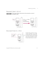
Страница 31: ...20 mA is selectable in setup mode The percentage scale is indicated on the primary display and the bar graph indicates the current value The 25 scale readout represents DC 5 mA at 0 20 mA and DC 8 mA at 4 20mA NOTE If the measured value is lower than 440 mA use the mA or μA current measurement mode Press to select AC current measurement mode Press at position ...

Страница 32: ... the frequency measurement display automatically after three seconds Measuring Resistance and Testing Continuity CAUTION Disconnect circuit power and discharge all high voltage capacitors before measuring resistance to prevent possible damage to the multimeter or the device under test Measurement range Beeper sound threshold 100 00 Ω 1 Ω 1000 0 Ω 10 Ω 10 000 kΩ 100 Ω 100 00 kΩ 1 kΩ 1 0000 MΩ 10 kΩ...

Страница 33: ...to 100 MΩ CAUTION Disconnect any circuit power and discharge all high voltage capacitors before testing diodes to prevent possible damage to the multimeter Reverse bias Forward bias NOTE The multimeter can display forward bias diode of up to approximately 1 1 V Typical forward bias diode ranges between 0 3 to 0 8 V with audible beeper sound ...

Страница 34: ...orrect capacitance value Ensure the polarity is correct when measuring polarized capacitors For measuring small capacitances press with the test leads open to subtract the residual capacitance of the multimeter and leads CAUTION Disconnect any circuit power and discharge all high voltage capacitors before measuring capacitance to prevent possible damage to the multimeter or the device under test T...

Страница 35: ...emperature is not constant do the following 1 Press for more than one second to enable 0 C compensation This function allows a quick measurement of the relative temperature 2 Avoid contact between the thermocouple probe and the measurement surface 3 After a constant reading is obtained press to set the reading as the relative reference temperature 4 Touch the measurement surface with the thermocou...

Страница 36: ... recorded 3 Press to scroll through maximum minimum or average present readings The MAX MIN AVG or MAXMINAVG annunciator lights up correspondingly to the displayed readings 4 Press for more than one second to exit MINMAX Recording mode NOTE The average value is the true average of all measured values taken in the MINMAX recording mode If an overload is recorded the averaging function will stop and...

Страница 37: ...h Hold mode The present value will be held and the annunciator is displayed 2 The multimeter is ready to hold new measuring value once the variation of measuring value exceeds the setting of variation count and the annunciator is flashed 3 The hold value will be updated until the measuring value is stable The annunciator will then stop flashing and an audible tone will sound to remind you 4 Press ...

Страница 38: ...ator is displayed 2 Press to view the stored reference value The NULL annunciator will flash for three seconds before the display returns to zero To exit this mode press while NULL is flashing on the display NOTE In resistance measurement the multimeter reads a non zero value due to the presence of test leads resistance Use the Null function to zero adjust the effect of test lead resistance In DC ...

Страница 39: ...al Logging To enable the Hand manual logging function select the Hand logging mode in Setup mode 1 Press Log for more than one second to store the present value and function on the primary display to memory 2 Press Log again for the next value that you want to save into memory see Figure 2 1 Table 2 1 Functions available for data logging Function Mode Range Voltage DC AC 1000 mV to 1000 V Current ...

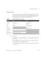
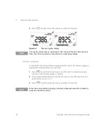
Страница 40: ... for more than one second to store the present value and function on the primary display to memory 2 The reading automatically logs into the memory in every interval as preset in Setup mode see Figure 2 2 3 Press Log for more than one second to exit this mode NOTE The maximum data that can be stored is 100 entries When the 100 entries are filled the FUL annunciator is indicated on the secondary di...

Страница 41: ...ress to select the first record or press to select the last record for quick navigation 3 Press to switch between hand manual and interval automatic logging review mode 4 Press View for more than one second to exit the Log View mode Removing Logged Data Press Log for more than one second at the respective Log Review mode hand or interval to clear all logged data in the memory NOTE The maximum data...

Страница 42: ...mediately See Chapter 4 Battery Replacement on page 50 To check the battery capacity see the following steps 1 Press BAT for more than one second to view the battery capacity The multimeter will resume back to normal function automatically after three seconds 2 The primary display illustrates the flashing bAt annunciator and the bar graph indicates the battery capacity in proportional percentage f...

Страница 43: ...erted to the A input terminal but the rotary switch is not set to the corresponding A location The display indicates a flashing AErr annunciator until the test lead is removed from the A input terminal Input mA Warning Alert The multimeter sounds an alerting beep when the μA mA input terminal detects a voltage level of more than 1 6 V The display indicates a flashing CErr annunciator until the tes...

Страница 44: ...2 Features and Functions 44 Keysight U1241AN User s and Service Guide THIS PAGE HAS BEEN INTENTIONALLY LEFT BLANK ...

Страница 45: ...User s and Service Guide 45 3 Default Settings Configurations Setting Configurations 46 This chapter describes on how to change and configure the default settings of the U1241AN handheld digital multimeter including data logging and other features ...

Страница 46: ...ng in Setup mode perform the following steps 1 Press or to scroll through menu items 2 Press or to scroll through available settings See Table 3 1 on page 47 for the details of each available option 3 Press Save to save the changes These parameters remain in the non volatile memory 4 Press and hold Setup for more than one second to exit Setup mode NOTE You will hear a beep when the multimeter is s...

Страница 47: ...z 600 Hz 300 Hz Sets frequency of beep sound of the multimeter 2400 Hz OFF Disables beep sound of multimeter t P Thermocouple tYPE Sets thermocouple type to K type tYPE K tYPE a Sets thermocouple type to J type tYPE mV Sets 100 mV measurement for T1 input Log Data logging Hand Enables manual data logging Hand 1 9999 s Sets interval for automatic data logging from 1 to 9999 seconds Press to toggle ...

Страница 48: ...rement unit to F d CF d F Sets temperature measurement to F d FC Sets temperature measurement to F pressing to change measurement unit to C d C Sets temperature measurement to C a To activate the multimeter after it has auto power off press any button to resume back to respective functional mode b To view Temperature t P menu press for more than one second Table 3 1 Available setting options in Se...

Страница 49: ...nstrument for Service 55 This chapter provides you with warranty services maintenance procedures and troubleshooting hints to solve general problems that you may encounter with the instrument Repair or service which are not covered in this manual should only be performed by qualified service personnel Please return to Keysight for product exchange if the product fails within the warranty period ...

Страница 50: ... 1 5 V x 4 batteries and uses only the specified battery type To ensure the specification specified it is suggested to replace the battery immediately when the low battery sign is displayed and flashing See the following procedures for battery replacement 1 At the rear panel turn the tilt stand to up side 2 Unscrew the battery cover notice the screw may not remove as loosed 3 Lift and remove the b...

Страница 51: ...ight U1241AN User s and Service Guide 51 5 Reverse the procedures of opening the cover to close the battery cover Figure 4 1 Battery replacement Battery Types ANSI NEDA IEC Alkaline 24A LR03 Zinc Chloride 24D R03 Battery cover screw ...

Страница 52: ...re 4 2 Fuse 1 replacement 5 If you want to replace a defective Fuse 2 remove Fuse 1 prior to removing the Fuse 2 Loosen the four screws shown in Figure 4 3 on page 53 to lift and remove the circuit board from top case 6 Gently remove the defective Fuse 2 by prying one end of the fuse loose and removing it out of the fuse bracket see Figure 4 3 on page 53 7 Replace a new fuse of the same size and r...

Страница 53: ... Figure 4 3 Fuse 2 replacement 8 Ensure that the rotary switch position is aligned with the align marking on the top case and circuit board switch stay on the OFF position 9 Then refasten the circuit board and the bottom cover respectively Fuse 2 11 A 1000 V Rotary switch ...

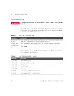
Страница 54: ... hints Malfunction Identification No LCD display after power ON Check the battery polarity and replace batteries if necessary Ensure that the replaced batteries are new batteries it is recommended not to mix old batteries with new batteries No beeper tone Check setup mode and verify if the beeper is set to OFF Then select the desired driving frequency Failed on current measurement Check the fuse T...

Страница 55: ... the instrument Do not include accessories unless they are associated with the failure symptoms 3 Protect the instrument by wrapping it in plastic or heavy paper 4 Pack the instrument in foam or other shock absorbing material and place it in a strong shipping container You are recommended to use the original shipping material or order materials from a Keysight Technologies Sales Office If both opt...

Страница 56: ...4 Service and Maintenance 56 Keysight U1241AN User s and Service Guide THIS PAGE HAS BEEN INTENTIONALLY LEFT BLANK ...
Страница 57: ...bration Process 62 Test Considerations 63 Performance Verification Tests 64 Calibration Security 68 Adjustment Considerations 71 Calibration Adjustments 73 Calibration Count 79 Calibration Errors 80 This chapter contains procedures of performance verification tests and calibration adjustments The performance tests is to ensure the multimeter is operating within its published specifications ...

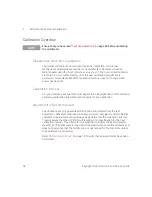
Страница 58: ...ration intervals beyond 2 years for any application Adjustment is Recommended Specifications are only guaranteed within the period stated from the last adjustment Whatever calibration interval you select Keysight recommends that complete re adjustment should always be performed at the calibration interval This will assure that the U1241AN will remain within specification for the next calibration i...

Страница 59: ...luke 5520A 1 5 instrument 1 year specifications DC Current Fluke 5520A 1 5 instrument 1 year specifications AC Voltage Fluke 5520A 1 5 instrument 1 year specifications AC Current Fluke 5520A 1 5 instrument 1 year specifications Resistance Fluke 5520A 1 5 instrument 1 year specifications Frequency Fluke 5520A 1 5 instrument 1 year specifications Capacitance Fluke 5520A 1 5 instrument 1 year specifi...

Страница 60: ...nction press to turn backlight ON at medium level of brightness intensity Press again to toggle the highest level of brightness intensity The backlight turns OFF automatically after setting period Alternatively you can press for the third time to turn the backlight OFF Testing the display To view all segments of the display press and hold the button while turning the rotary switch from OFF to any ...

Страница 61: ...y indicates a flashing AErr annunciator until the test lead is removed from the A input terminal Input mA Terminal Alert Test This test determines if the detected input voltage level is within the accepted boundaries when the μA mA input terminal is connected The multimeter sounds an alerting beep when the μA mA input terminal detects a voltage level of higher than 1 6 V The display indicates a fl...

Страница 62: ... 3 Unsecure the multimeter for calibration see Calibration Security on page 68 4 Prior to performing the adjustments see Adjustment Considerations on page 71 5 Perform the adjustment procedures see Calibration Adjustments on page 73 6 Secure the multimeter against unauthorized calibration see Exiting Adjustment Mode on page 78 Ensure that the multimeter has quit the Adjustment Mode and turned off ...

Страница 63: ...nce verification test ensure that the multimeter has been switched ON and placed in the test environment for at least one hour with a J K type thermo couple connected between the multimeter and calibration source Allow one minute warm up period with a Shorting Plug connected to the V and COM input terminals Use shielded twisted pair Teflon insulated cables to reduce settling and noise errors Keep ...

Страница 64: ...me performance during calibration Performance Verification Tests The performance verification tests are recommended as acceptance tests when you first receive the multimeter The acceptance test results should be compared against the one year test limits After acceptance you should repeat the performance verification tests at every calibration interval If the multimeter fails performance verificati...

Страница 65: ...0 0 V 1 1 V 2 Press to go to function 1000 mV 1000 0 mV 1 kHz 10 4 mV 1000 0 mV 2 5 kHz 20 4 mV 1000 0 mV 20 kHz 20 4 mV 10 V 10 000 V 1 kHz 104 mV 10 000 V 2 5 kHz 204 mV 10 000 V 20 kHz 204 mV 100 V 100 00 V 1 kHz 1 04 V 100 00 V 2 5 kHz 2 04 V 100 00 V 20 kHz 3 03 V 1000 V 1000 0 V 1 kHz 10 4 V 1000 0 V 2 5 kHz 30 3 V 3 Press to go to frequency mode 100 Hz 1 000 V 70 Hz 31 mHz 1000 Hz 1 000 V 1...

Страница 66: ...103 mF 7 Turn the rotary switch to position 1000 µA 1000 0 µA 2 3 µA 10000 µA 10000 µA 23 µA 8 Press to go to function 1000 µA 1000 0 µA 2 kHz 10 2 µA 10000 µA 10000 µA 2 kHz 102 µA 9 Turn the rotary switch to position 100 mA 100 00 mA 0 23 mA 440 mA 400 0 mA c 1 1 mA 10 Press to go to function 100 mA 100 00 mA 2 kHz 1 02 mA 440 mA 400 mA c 2 kHz 4 2 mA 11 Turn the rotary switch to position 10 A 1...

Страница 67: ...ultimeter to cool down for 60 seconds before applying low current measurement e Set both Fluke 5520A and multimeter to internal reference Prior to performing measurements connect one end of the K type thermocouple with miniature TC connector on both ends to the 5520A TC output and the other end to a precision thermometer to verify that the source outputs the desired value Adjust the source accordi...

Страница 68: ...when the multimeter is shipped from the factory The security code is stored in non volatile memory and does not change when power is off Unsecuring the multimeter from the front panel 1 Turn the rotary switch to 2 Press and simultaneously to enter the Calibration Security Code entry mode The primary display shows 5555 and the secondary display shows SEU 3 Press or to step each character in the cod...

Страница 69: ...ation security code 1234 will be displayed on primary display 3 Press or to step each character in the code Press or to change the value of the selected character 4 Press Save button to store new calibration security code 5 If the new calibration security code has been successfully stored the secondary display will show PASS If the new code failed to save the multimeter will shows error code E07 o...

Страница 70: ...he value of the selected character 6 Set the last 4 digit serial number of the multimeter Press Save to confirm the entry 7 If the 4 digit serial number entered is correct the secondary display will show PAS If an invalid code is entered the multimeter will shows error code E03 Ensure that the last 4 digit serial number is entered correctly and repeat the step 1 to 7 Using the Front Panel for Adju...

Страница 71: ...r during the adjustment Replace the batteries to avoid inaccurate readings 3 Consider the thermal effects of the test leads connected to the calibrator and multimeter It is recommended to wait for one minute before start performing the calibration 4 During ambient temperature adjustment ensure that the multimeter has been turned on for at least one hour with K type thermocouple connected between t...

Страница 72: ...ion memory for the present function Table 5 3 Valid adjustment input values Function Range Valid Input Reference Values 1000 mV 10 V 100 V 1000 V 0 9 to 1 1 x full scale 1000 mV 10 V 100 V 1000 V 0 9 to 1 1 x full scale 1 V 0 9 to 1 1 x full scale 1000 Ω 10 kΩ 100 kΩ 1000 kΩ 10 MΩ 0 9 to 1 1 x full scale 1000 nF 10 μF 100 μF 1000 μF 10 mF 0 9 to 1 1 x full scale 1000 μA 10000 μA 0 9 to 1 1 x full ...

Страница 73: ... the and arrow keys to select the calibration range Cal Range 5 Apply the input signal as shown in the Input Reference Value column of the Table 5 3 The bar graph will display the input reading There is no bar graph display for temperature adjustment T1 0 C Ensure that 0 C with ambient compensation is provided DCmV T1 100 mV 0 9 to 1 1 x full scale Table 5 3 Valid adjustment input values continued...

Страница 74: ...he calibration error number appears in the secondary display The primary display remains at the current Cal Item 9 Turn the rotary switch to the next function according to the Test Function column shown in Table 5 3 Repeat step 3 to step 8 for each adjustment point shown in the calibration adjustment see Table 5 4 10 Verify the adjustments using the Performance Verification Tests on page 64 NOTE Y...

Страница 75: ...V 1000 0 mV 10 V 10 V 10 000 V 100 V 100 V 100 00 V 1000 V 1000 V 1000 0 V 2 Press to go to function 1000 mV 30 mV 70 Hz 30 0 mV 1000 mV 70 Hz 1000 0 mV 1000 mV 10 kHz 1000 0 mV 10 V 0 5 V 70 Hz 0 500 V 10 V 70 Hz 10 000 V 10 V 10 kHz 10 000 V 100 V 5 V 70 Hz 5 00 V 100 V 70 Hz 100 00 V 100 V 2 5 kHz 100 00 V 1000 V 50 V 70 Hz 50 0 V 1000 V 70 Hz 1000 0 V 1000V 1 kHz 1000 0 V 3 Turn the rotary swi...

Страница 76: ...0 Ω 1000 Ω 1000 Ω 5 Turn the rotary switch to position Open Input terminals open remove all test leads and shorting plugs from input terminals oPEn 1000 nF 400 nF 400 0 nF 1000 nF 1000 0 nF 10 μF 10 μF 10 000 μF 100 μF 100 μF 100 00 μF 1000 μF 1000 μF 1000 0 μF 10 mF 10 mF 10 000 mF 6 Turn the rotary switch to position Open Input terminals open remove all test leads and shorting plugs from input t...

Страница 77: ...000 mA 320 mA 320 0 mA 9 Press to go to function 100 mA 5 mA 70 Hz 5 00 mA 10 mA 70 Hz 10 00 mA 100 mA 70 Hz 100 00 mA 1000 mA 100 mA 70 Hz 100 0 mA 320 mA 70 Hz 320 0 mA Move the test lead from μA mA and COM terminal to A and COM terminal Caution Connect the calibrator to the multimeter s A and COM terminal before applying 10 A 10 Turn the rotary switch to position Open Input terminals open remov...

Страница 78: ...ress to go to func tion 100 mV 3 mV 70 Hz 3 00 mV 100 mV 70 Hz 100 00 mV 14 Press to go to T1 function a K type 0 ºC 000 0 ºC a Set the 5520A to internal reference Prior to performing adjustment connect one end of the K type thermocouple with miniature TC connector on both ends to the 5520A TC output and the other end to a precision thermometer to verify that the source outputs the desired value A...

Страница 79: ...ount will reset to 0 The calibration count can be read from the front panel after the multimeter has been unsecured 1 In adjustment mode press and hold for more than one second to view the calibration count viewing mode The primary display indicates the calibration count value while the secondary display indicates Cnt 2 Take note of the calibration count to keep track of the number of calibration ...

Страница 80: ...secondary display Table 5 5 Calibration error codes Code Descriptions 200 Calibration error Calibration mode is secured E02 Calibration error Invalid secure code E03 Calibration error Invalid serial number code E04 Calibration error Calibration aborted E05 Calibration error Value out of range E06 Calibration error Signal measurement out of range E07 Calibration error Frequency out of range E08 EEP...

Страница 81: ...eter User s and Service Guide 81 6 Specifications and Characteristics For the characteristics and specifications of the U1241AN Handheld Digital Multimeter refer to the datasheet at http literature cdn keysight com litweb pdf 5989 7040EN pdf ...

Страница 82: ...6 Specifications and Characteristics 82 Keysight U1241AN User s and Service Guide THIS PAGE HAS BEEN INTENTIONALLY LEFT BLANK ...

Страница 83: ...MC 7 equipotentiality 3 F fast acting 27 flammable 4 fragile 55 front panel 22 fuse 52 H housing 54 humidity 7 63 I IEC 7 input connections 64 terminal 26 values 72 insulation 4 introduction 20 J J type 47 64 K key features 20 keypad 25 K type 47 L logging interval 40 manual 39 M maintenance 50 measuring Scale 31 capacitance 34 current 30 frequency 32 resistance 32 temperature 35 test continuity 3...

Страница 84: ...y 3 scale 31 security 68 serial 55 80 shipping 21 switch counter 25 symbols 3 T test connections 64 equipment 59 function 65 verification 64 thermocouple 47 timer 47 tips 34 35 trigger hold 37 troubleshooting 54 True RMS 20 W warm up 63 warning 43 WEEE 8 ...

Страница 85: ...on is subject to change without notice Always refer to the Keysight website for the latest revision Keysight Technologies 2008 2016 Edition 9 July 30 2016 Printed in Malaysia U1241 90038 U1241 90038 www keysight com ...

Отзывы: