19
Getting Started
STEP 3. Install the Network Analyzer Modules
M9341A (Digital I/O) and M9379A (RF Amplifier) Installation
M9485A can work with M9341A Digital I/O and M9379A RF Amplifier. Here
is the limitation of module
M9379A Installation:
• Empty slot is not allowed between source module and last receiver
modules.
• When M9379A is installed between receivers, the sync signal connection
at the front panel between M9379A and M9376A/77A is necessary.
• Refer to Online Help > Programming > I/O Connector (M9845A) >
Example 5 and 6.
WARNING
When connecting or disconnecting a cable to the M9379A module, do not touch the open
end of the cable. Doing so may damage the module by electrostatic discharge (ESD).
M9341A Installation:
• Only one M9341A can be installed in a chassis.
2-Way Divider and 4-Way Divider Installation
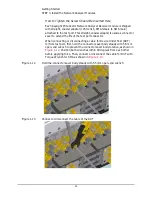
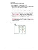
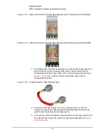
a. Upon placing all the modules into the chassis, if you are using dividers,
fasten the modules only after alignment plate is installed.
shows the installation of the M9376-60016 4-Way alignment
plate on the modules.
b. Only after the alignment plate is installed, the black plate cover should
be removed. 2-port module have the option of using M9376-60014
2-Way alignment plate.
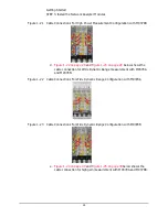
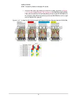
c. Next, fasten the M9376-62006 4-way divider by ensuring that the
SMP-SMP adapter are fit well through the alignment plate, as shown in
. 2-port modules have the option of using 3 of the
M9376-62004 2-way divider.Confirm that the screws on 2/4 way divider
are fasten firmly.
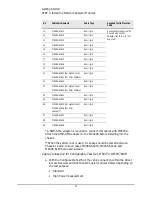
d. In the case of Standard Receivers M9376A only, 4-port modules requires
3 of the 4-way divider to be connected. Similarly, 8-port modules require
6 of the 4-way divider and 12-port modules require 9 of the 4-way
divider.
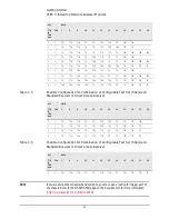
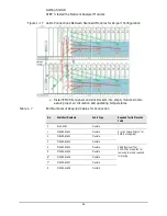
e. In the case of Configurable Test Set, there are several options of divider
combinations. Refer to
“Configurable Test Set (M9377A and M9378A/B)
for the full combinations.
Содержание M9300A
Страница 4: ...4 Contents ...
Страница 42: ...42 Getting Started STEP 5 Verify Operation of the Network Analyzer Modules ...


