KD-MSV8X8 Operating Instructions
Page
KD-MSV8X8 Operating Instructions
Page
Operation
After performing the setup above, the unit is ready for operation. When the unit is initially powered
on all LED indicators are off until either:
An RS-232 command is issued
IR power on is issued
Any front panel button is pressed
Most applications will involve only input switching for day-to-day operation. There are a several
options for controlling the unit. Commands can be issued via IR remote control, RS-232 or simply
by using the front panel buttons. Keep in mind that controlling the unit in a 4 input/4 output
RGBHV setup requires concurrent switching of two inputs and two outputs for each input source
and output zone.
Front Panel Control
For switching inputs, simply press the ‘Input Select’ button within the desired output section. See
number 1 on Figure 4. Pressing this button repeatedly will cycle through all video inputs.
IR (Remote Control)
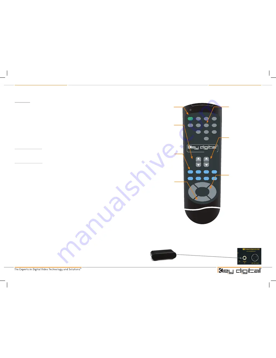
The KD-MSV8X8 ships with an IR remote control providing selection of inputs for every output. As
illustrated in the following diagram, these convenient keys are clearly marked.
To issue a command via IR to switch inputs, issue the following sequence:
1.
First, press the button labeled ‘R1’
2.
Next, press the buttons for the unit’s address [00-99]. Factory default is 00
>
When multiple units are used in a system, unique unit addresses allow for error free switching,
ensuring that only the addressed unit ‘listens’ to the command issued. This is especially
helpful in IR control situations.
3.
Then, press the ‘Output Select’ rocker style button up or down to select the desired output to
switch. Note that the LED’s will flash, indicating selected output.
4.
Next, press the ‘Input Select’ rocker style button up or down to select the desired input. Note
that the LED’s will indicate selected input.
5.
Finally, press the ‘R1’ button to complete the sequence. Note that the LED indicators will flash
for 30 seconds or until ‘R1’ is pressed. Whenever the LED’s are flashing, the status of that
output can be switched and no other output can be changed. To end one sequence and begin
another, press ‘R1’ or wait 30 seconds for LED’s to stop flashing.
Alternatively, the output and input selection in steps 3 and 4 above can be made in the
following manner.
3.
Press the number keypad buttons [01~08] to select the desired output to switch. Note that the
LED’s will flash, indicating selected output.
4.
Then, press the number keypad buttons [01~08] to select the desired input. Note that the LED’s
will change, indicating selected input.
For all IR commands, the steps 1 and 2 above must be issued first to address the unit.
See the following button labels for IR commands.
›
›
›
IR Extender
You may also want to use an IR extender, such as available by Xantech:
A rear panel sensor is perfect for use with Xantech IR extender
A wired IR serial connector is also provided
You’ll need to either mount the IR extender on the side of the KD-MSV8X8 unit,
or connect the serial connector cable.
›
›
Figure 5: IR Remote Buttons
www.keydigital.com
1
2
3
4
5
6
7
8
9
0
Power ON
Power OFF
Input
Select
Output
Select
Mute
Channel
Restore
Channel
Mute
All
Restore
All
R1
R2
R3
R6
R5
R7
R4
R8
KD-REMOTE8x8RCA
Part Number:
1
2
3
4
5
6
7
8
9
0
Power ON
Power OFF
Input
Select
Output
Select
www.keydigital.com
Mute
Channel
Restore
Channel
Mute
All
Restore
All
R1
R2
R3
R6
R5
R7
R4
R8
Power On and
Off buttons
numeric Keypad
See steps 3 and 4 above
Input Select button
Issue the unit address and
select output (see steps
1-3 above), then press this
rocker type switch up or
down to select desired input
R1 Button
Press this button
to begin the unit
address command.
See step 1 above
Wired IR Extender
KD-MSV8X8 Unit
3.5mm male-to-male mono cable
www.keydigital.com
1
2
3
4
5
6
7
8
9
0
Power ON
Power OFF
Input
Select
Output
Select
Mute
Channel
Restore
Channel
Mute
All
Restore
All
R1
R2
R3
R6
R5
R7
R4
R8
KD-REMOTE8x8RCA
Part Number:
1
2
3
4
5
6
7
8
9
0
Power ON
Power OFF
Input
Select
Output
Select
www.keydigital.com
Mute
Channel
Restore
Channel
Mute
All
Restore
All
R1
R2
R3
R6
R5
R7
R4
R8
Output Select button
Issue the unit address (see steps
1 and 2 above), then press this
rocker type switch up or down to
select desired output
Mute/Restore
Channel buttons
To mute one output channel,
issue the unit address (step 1
and 2 above), then press ‘Mute
Channel’ followed by desired
output channel [01~08]. To
un-mute (restore) one output
channel, issue the unit address
then press ‘Restore Channel’
followed by desired output
channel
Mute/Restore
All buttons
To mute all output channels,
issue the unit address (step
1 and 2 above), then press
‘Mute All’. To un-mute
(restore) all output channels,
issue the unit address then
press ‘Restore All’
KD-MSV8x8_Manual.indd 6-7
8/30/07 3:55:24 PM


