33
• All the screens shown in the figures of this chapter correspond to
a 1kVA equipment, as an example. For more details of lCD screen
shoots from control panel, see the next section 6.2.
6.2.
operating modes of the equipment
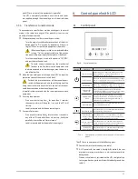
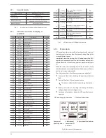
• The different graphical symbols displayed in the lCD of the
control panel, correspond to the following operating modes or
status:
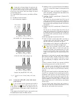
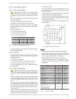
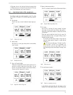
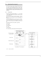
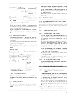
normal mode:
The UPS is running on normal mode with power supply pre-
sent.
Fig. 22. normal mode screen.
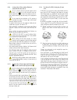
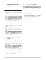
battery mode:
when the UPS is running on battery mode, the alarm beeps
every 4 seconds.
Fig. 23. battery mode screen.
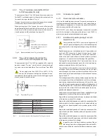
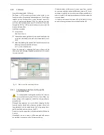
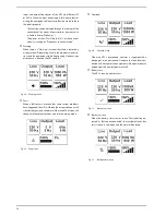
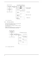
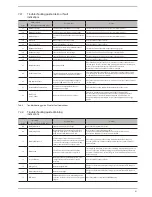
bypass with output voltage:
The output voltage that feeds the load comes from the com-
mercial mains directly through the internal filters. This way
the loads are not protected against mains faults or blackouts.
The acoustic alarm beeps every 2 minutes.
Fig. 24. bypass with output voltage screen.
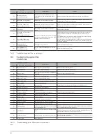
bypass without output voltage:
The UPS is running on bypass mode without output voltage.
Fig. 25. bypass without output voltage screen.
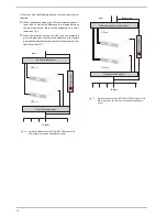
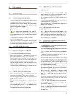
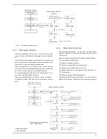
ECo mode:
once the UPS is started up, the energy that feeds the load/s
comes from the commercial mains directly through the in-
ternal filters, meanwhile the voltage is inside the limits that are
set as normals.
when input power supply fails, due to fault or wrong, the
equipment will transfer from "line mode" to "battery mode"
to supply the load/s properly.
– This function can be activated through the control panel
(by means of password) or through a suitable software
(winPower, ...)
–
The transfer time between "ECo mode" and "bat-
tery mode" is around 10 ms. nevertheless, this
time can be excessive for some type of loads, so the ECo
mode operating has to be considered according to this
issue.
Fig. 26. ECo mode screen.
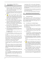
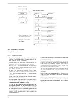
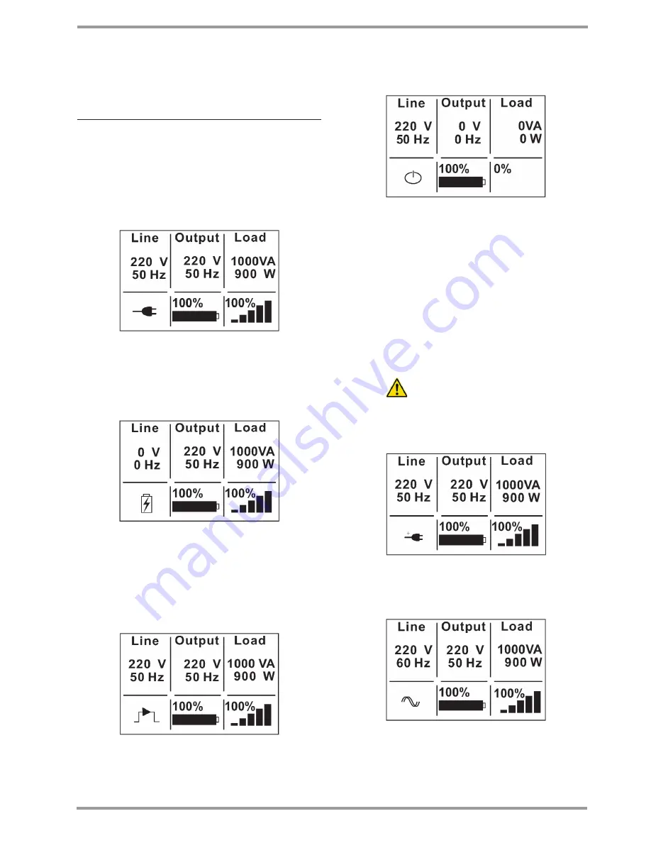
Frequency converter mode
Fig. 27.
Frequency converter mode screen.
in the frequency converter mode, the static bypass is disa-
bled and any of the operating modes of itself, because the

