18
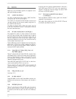
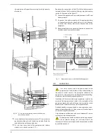
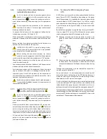
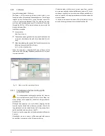
by means of the supplied screws "E".
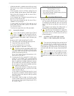
For equipments of higher power.
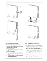
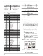
Put the equipment and battery module in vertical position
and together. next fix the two metallic supports by means of
the supplied screws, one on the side of the equipment and
other one on the side of the battery module, in the UPS 4 to
6 kVA.
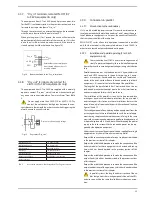
For equipment of 8 to 10 kVA, put the equipment vertical.
There are not supports or stabilizers.
Fix the joint metallic piece between the UPS and battery
module by means of the supplied screws.
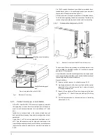
"A"
"A"
"b"
"C"
"F"
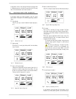
Fig. 8.
Model in vertical -tower type- assembling with extended
back up time (battery module).
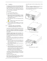
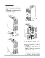
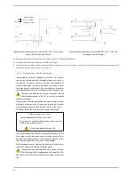
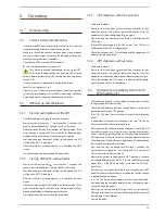
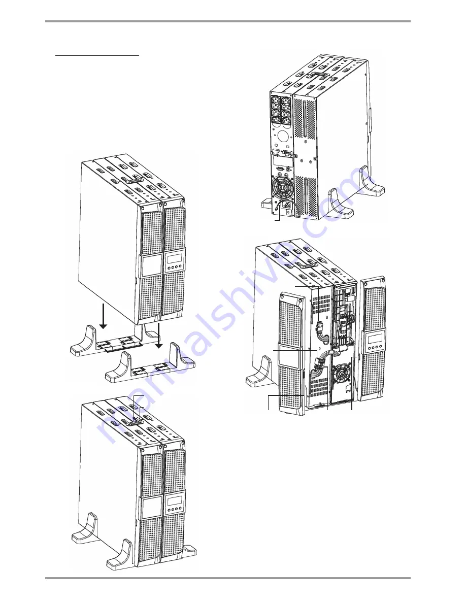
• Regarding the connections of the UPS with the battery module
in models up to 6 kVA, make the following steps, but reading sec-
tion 4.3.4 previously:
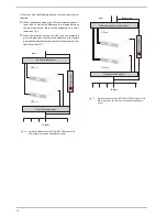
Connect the supplied earth joint cable "F", between the UPS
and battery module.
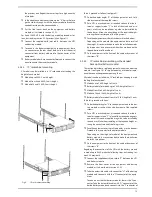
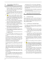
Remove the front cover of the equipment and battery
module, as it is described in section 4.2.5.2.
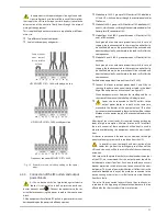
Take the extensible cable with connector "H" of the battery
module and connect it with the "G" connector of the equip-
ment.
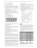
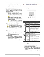
To connect it with other battery modules, there is the "J" con-
nector. Take the extensible cable with "H" connector of the
beside battery module and connect it to the "J" connector of
"H"
"J"
"G"
"K"
"K"
"D"
"E"

