background image

6

228-1915

 053119

KEPCO, INC. 



 131-38 SANFORD AVENUE 



  FLUSHING, NY. 11355 U.S.A.



  TEL (718) 461-7000



 FAX (718) 767-1102

http://www.kepcopower.com   



 email: [email protected]

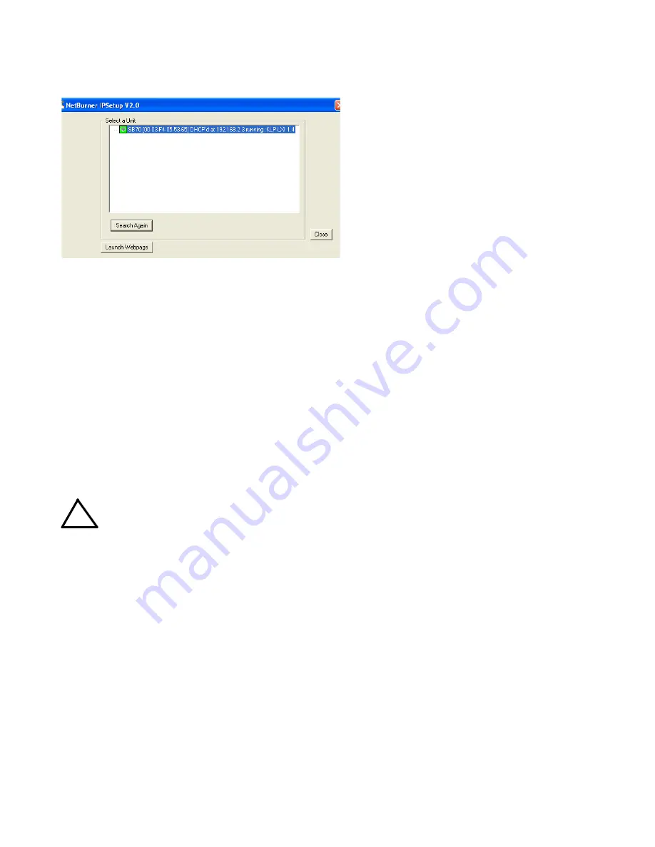
FIGURE 2.  PS FIND SCREEN

RS 232 CONNECTIONS. 

Connect the BOP 2KW

to a modem using a Null Modem patch cable at the RS
232 port located on the rear panel (See Figure 6). A
Null Modem cable is not required for older MAC com-
puters with D-sub serial port in which the RXD and
TXD line transposition is accomplished via external
hardware. The default baud rate is 9600; refer to the
Operator Manual to change it.

VIII — OPERATION.

Refer to Figures 3 and for the function of front panel
controls and indicators for the 

control and power

boost sections

, respectively.

Additional features covered in the Operator Manual
are: Quick Boot (eliminating the power- up displays),
use of the internal relay, operation via the LAN inter-
face or analog signals and setting coarse/fine adjust-
ment preference of the VOLTAGE and CURRENT
controls. An Installation/Operation Summary is also
included in the Operator Manual. The Operator Manual
also covers the GPIB, Ethernet and RS 232 interfaces,
including the use of the drivers downloadable from: 

www.kepcopower.com/drivers/drivers-dl3.htm#bop1k.

TURNING THE POWER SUPPLY ON. 

CAUTION: 

DO NOT repeatedly toggle the cir-
cuit breaker/switch as this may
damage the unit. 

Set POWER ON/OFF circuit breaker/switch on front
panel to ON. If actuator does not lock when released,
wait a few seconds before trying again. The circuit
breaker is “trip-free” design; if overload exists, contacts
cannot be held closed by actuator.

When the power supply is turned on, it per-
forms a brief self-test that includes testing the
three processors (analog, interface and dis-
play) and an inter-module test, then displays
the power-up screen (see Figure 5). If an error
is detected, the FAULT indicator will light,
information about the error will be briefly dis-
played on the LCD.

If the unit powers up in REMOTE mode, press

!

 to set the unit to LOCAL mode.

If the display is not viewable, press 

#

 twice.

The display will cycle through the range of
contrast settings. Press 

#

 again to lock in

the preferred contrast. 

ACCESSING THE MENUS. 

From the power-up

screen, pressing the Function keys indicated on the
LCD opens the associated menu. The menu opened
may list submenus that may be opened either directly
by pressing the associated Function keys, or by high-
lighting an item on the list and pressing the View/Mod-
ify function key. Menus and submenus will display a list
of parameters, with the top one highlighted. The func-
tion key assignments can vary, but generally offer the
following choices:

!

 allows the highlighted parameter to be

viewed or modified. After changing the param-
eter, the following choices are available: 

$

 -

SAVE or 

ENTER

 to save the change, 

%

  -

EXIT to abort the change and exit to the previ-
ous menu.

@

 - RESTORE DEFAULT restores factory

defaults for the parameters displayed (except
for GPIB address). The factory defaults may
be saved as power-up defaults by pressing

$

.

#

 - The function varies, depending on the

menu. In most cases 

#

 is used to abort a

change without applying the modified setting.
From the power-up screen 

#

 is used to

adjust contrast. In the Revisions/TEST sub-
menu of the General Setup Menu, 

#

 is used

to execute a test. 

!

Содержание BOP 10-200ME

Страница 1: ...ing instructions including an Installation Operation Summary which includes hyperlinked references to detailed procedures but which can be printed as a handy reference The BOP 2KW MG ME Operator s Man...

Страница 2: ...ering many electrochemical reactions Models with L suffix have been optimized for exceptionally low current ripple and noise and improved stability drift and temperature making them ideal for driving...

Страница 3: ...th displayed voltage on LCD within 0 05 of rated maximum voltage VI ACCESSORIES See Table 3 TABLE 3 ACCESSORIES ITEM FUNCTION PART NUMBER Mating Connector Trigger Mates with Trigger port 142 0527 Kepc...

Страница 4: ...4 228 1915 053119 KEPCO INC 131 38 SANFORD AVENUE FLUSHING NY 11355 U S A TEL 718 461 7000 FAX 718 767 1102 http www kepcopower com email hq kepcopower com FIGURE 1 BOP OUTPUT CHARACTERISTICS...

Страница 5: ...Terminal Block Then connect OUT S and COM S lines from the BOP 2KW Sense Monitor Terminal Block to the load see Figure 7B using 22 AWG wire twisted pair ANALOG I O CONNECTIONS The Analog I O Port conn...

Страница 6: ...load exists contacts cannot be held closed by actuator When the power supply is turned on it per forms a brief self test that includes testing the three processors analog interface and dis play and an...

Страница 7: ...con figuration shown as a power up setting so the changes will not be lost when the unit is turned off APPLY EXIT applies the current changed setting without saving for power up and exits to the previ...

Страница 8: ...AVENUE FLUSHING NY 11355 U S A TEL 718 461 7000 FAX 718 767 1102 http www kepcopower com email hq kepcopower com FIGURE 4 BOP 2KW SERIES POWER BOOST SECTION FRONT PANEL CONTROLS AND INDICATORS FIGURE...

Страница 9: ...o incre ment or decrement the highlighted digit Pressing ADJUST while rotating adjusts the least significant digit If the output is on unit not in Standby changes made using the ADJUST control are imm...

Страница 10: ...channel is determined by the MODE key in local mode which alternately selects either Voltage mode or Current mode or by SCPI com mand in digital remote mode The protection channel is determined automa...

Страница 11: ...l are possible Otherwise the value entered is applied to both positive and negative protect channels NOTE The BOP can be configured to show the protection limits as either a single value that applies...

Страница 12: ...loads Table 4 indicates how the power supply responds to a command to go from Output ON to OFF When the output is disabled the unit is set to voltage mode voltage is set to zero and both current prot...

Страница 13: ...opened after the connections are complete and then the switch in series with the battery should be closed If the constant voltage type active electronic load is adjusted to zero before handling the p...

Страница 14: ...com mands via RS 232 GPIB or LAN ports opera tion via web pages Analog Remote Operation via Analog I O port Details about Protect Limits and Software controlled limits Storing Recalling Power Supply...

Страница 15: ...15 15 KEPCO INC 131 38 SANFORD AVENUE FLUSHING NY 11355 U S A TEL 718 461 7000 FAX 718 767 1102 http www kepcopower com email hq kepcopower com FIGURE 9 BOP 2KW OUTLINE DIMENSIONS Sheet 1 of 2 REAR VI...

Страница 16: ...NY 11355 U S A TEL 718 461 7000 FAX 718 767 1102 http www kepcopower com email hq kepcopower com FIGURE 10 BOP 2KW WIRING DIAGRAM DETAIL A S MON OUT OUT MON COM GND GND NET OUT MON N C OUT S COM S CO...

Отзывы: