8
2.2.2 Grounding Requirements
Chassis ground must be used. DC ground (Terminal 2) is not directly
coupled to Earth ground internally. It is preferable not to ground DC
negative return to chassis ground, pin 3, as poor site earths can
introduce noise into a system, but if necessary an earth connection
should be made, from the power supply return point to the central star
earth point.
Ground conductors should be as short and as large in size as possible.
The conductors must always be large enough to carry the maximum
short circuit current of the path being considered. Ground conductors
should be connected from a tree from a central star earth ground point.
This ensures that no ground conductor carries current from any other
branch.
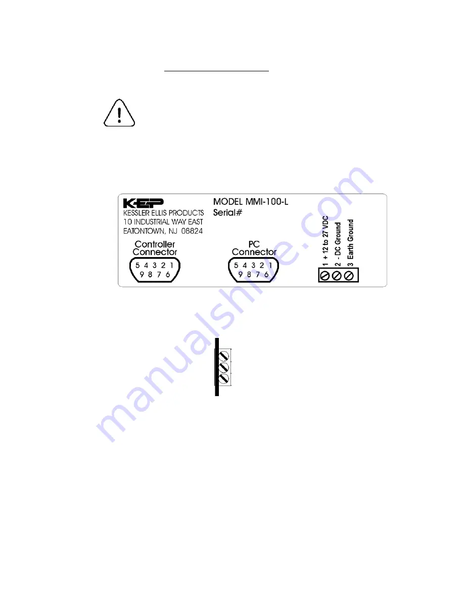
Typical Label on Rear of MMI-1XX Series unit.
+12 to 27 VDC Wiring Diagram
View from top of connector
3 Earth Ground
2 - DC Ground
1 + 12 to 27 VDC
2.2.3 CE Requirements
To make the MMI comply with EMC directives, and to reduce susceptibility to electrical interference, a
separate #14 AWG ground wire should be taken to terminal 3 of the power connector. This
ground connection should be run directly to the central star earth connection point (as
recommended in most PLC Installation Instructions).
Содержание MMI-1 Series
Страница 2: ......


