TKR-D710
48
●
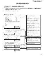
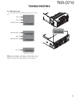
When an error display appears on the LED segment indicator.
The display indicates “E 1 ”
Appears when all Channel Data is blank.
Please set the channel data.
The display indicates “E 2 ”
Appears when the selected Channel is blank.
(When a blank channel is selected with Remote
Control, etc.)
Please set the channel data.
●
Checking the signal output from
the ASIC via software control
●
Panel control (Control unit)
It is unlikely that the BGA parts are broken.
Points to be checked
Normal voltage
SB L317
“Power Supply Voltage”
– 0.4V or more
Points to be checked
Normal voltage
SBC R241
3.3V
The BGA parts are not broken.
IC503~IC507 may be broken.
If the SBC is 3.3V and SB L317 is “Normal voltage”,
the BGA parts are not broken.
Remove R241. If the ASIC side is 0V,
the ASIC/ SRAM may be broken.
●
Panel control (Display unit)
Checking voltage
Points to be checked
Normal voltage
VDD IC506 (2 pin), IC507 (2 pin)
5.0V
Points to be checked
Normal voltage
SOE CN502 (11 pin)
5.0V
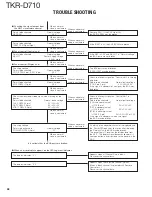
Check the follows signal on “Control Unit” in turning
on power.
Points to be checked
Normal pulse voltage
IC19 (2 pin, 3 pin)
3.3V
→
0V
→
3.3V
If the signal is abnormal or no signal, the BGA may
be broken.
Check the clock/data/strobe signal when turning on the
power.
Points to be checked
Normal pulse voltage
CLK CN502 (14 pin)
0V
→
5V
→
0V
DAT CN502 (15 pin)
0V
→
5V
→
0V
STB1 CN502 (13 pin)
0V
→
5V
→
0V
Checking voltage
Points to be checked
Normal voltage
POWLEDC IC502 (4 pin)
5V
If nothing or an abnormal character is displayed and
the Power LED does not light even after replacing
the Display Unit, the BGA may be broken.
The panel Logic IC receives the display data from
the ASIC. The display signal becomes abnormal if
communication is incorrect due to the trouble in the
ASIC.
Points to be checked
Normal voltage
/DRST C38 (Signal Side)
3.3V
If the /DRST is 0V, the ASIC/SRAM are broken.
When a normal
value is confirmed.
When a normal
value is confirmed.
When a normal
value is confirmed.
When a normal
value is confirmed.
When a normal
value is confirmed.
When a normal
value is confirmed.
When a normal
value is confirmed.
When a normal
value is confirmed.
When an abnormal
value is confirmed.
When an abnormal
value is confirmed.
When an abnormal
value is confirmed.
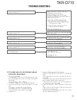
Check the follows signal on “Control Unit” in
powering on.
Points to be checked
Normal pulse voltage
[CLK is abnormal value.]
→
IC18 (6 pin)
0V
→
3.3V
→
0V
[DAT is abnormal value.]
→
IC18 (8 pin)
0V
→
3.3V
→
0V
[STB1 is abnormal value.]
→
IC26 (1,2 pin)
0V
→
3.3V
→
0V or 3.3V
If the signal is abnormal value or no signal,
the BGA may be broken.
When an abnormal
value is confirmed.
When an abnormal
value is confirmed.
When an abnormal
value is confirmed.
When an abnormal
value is confirmed.
TROUBLE SHOOTING
Содержание TKR-D710
Страница 71: ...TKR D710 71 MEMO ...
Страница 108: ...TKR D710 108 MEMO ...
Страница 110: ...Printed in Japan No RQ148 Communications Systems Business Operation ...


