TKR-D710
13
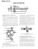
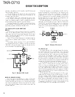
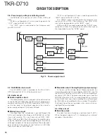
volume control circuit. The 2nd electronic volume control
circuit adjusts the modulating signal and is fed to IC606.
IC603 is an inverting amplifi er for inverting the amplifi -
cation of the modulating signal. The output of IC603 and
the charge pump output of IC602 (Transmitter modulation
16.8MHz PLL IC) are synthesized by IC604 and is fed to
VCXO (X600).
IC606 is a non-inverting amplifi er. The output of the 2nd
electronic volume control circuit is amplifi ed by IC606 and is
fed to the transmitter main PLL circuit.
AMP
IC604
AMP
IC606
AMP
IC603
VREF
IC605
EVOL
IC804
X58-5200-10
X600
MB
MOD
CN800
MO
OSC
16.8MHz
TX VCO
/PLL
Fig. 5 Modulation level adjustment circuit
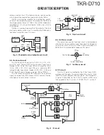
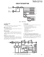
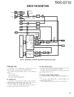
2-5. Front-end circuit
The front-end circuit consists of LPF, L111, L112, L114,
and L115 coils, former BPF tuning Variable Capacitance
Diodes (D105, D106, D107 and D108), RF amplifier Q101
(LNA), L100, L101, L103, and L104 coils, and latter BPF
tuning Variable Capacitance Diodes (D100, D101, D103 and
D104). The BPF covers frequency ranges 136 to 174MHz.
The LPF, former and latter BPF attenuate the unwanted
signals receiving from RX antenna (CN101) and only the de-
sired signals transmit to the 1st-mixer.
LNA AMP
Q101
Buffer
IC100
Buffer
IC101
136~
174MHz
BPF
EVOL
IC804
BPF
LPF
RX ANT
CN101
136~
174MHz
Fig. 6 Front-end circuit
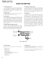
2-6. 1st-Mixer circuit
The signal passing the front-end circuit is heterodyned
with the fi rst local oscillator signal from the PLL frequency
synthesizer circuit at the first mixer (IC300) to become a
58.05 MHz fi rst intermediate frequency (IF) signal.
1st Local
194.05~232.05MHz
Mixer
IC300
136~174MHz
IF1
58.05MHz
Fig. 7 1st-Mixer circuit
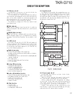
2-7. IF circuit
The fi rst IF signal is amplifi ed by the IF Post Amp (Q301)
and passed through a four-pole monolithic crystal filter
(XF300) to reject adjacent channel signals. The fi ltered fi rst
IF signal is amplified by the IF AGC amplifier (Q300) and
then applied to the IF system IC (IC403). The IF system IC
SW
450kHz
RSSI
CN802
58.05MHz
IF IC
IC403
IC405
SW
IC406
CF402
CF403
CF401
SW
IC408
SW
IC407
CF400
RSSI
IF2
IF1
2nd Lo
57.6MHz
IF AMP
IC404
IF AMP
IC400
MCF
XF300
IF AGC AMP
Q300
POST AMP
Q301
Diff AMP
IC401(B/2)
AMP
IC409(A/2,B/2)
Buffer
IC401(A/2)
Fig. 8 IF circuit
CIRCUIT DESCRIPTION
Содержание TKR-D710
Страница 71: ...TKR D710 71 MEMO ...
Страница 108: ...TKR D710 108 MEMO ...
Страница 110: ...Printed in Japan No RQ148 Communications Systems Business Operation ...


