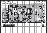
TKR-850
40
Item
Condition
Measurement
Adjustment
Specifications/Remarks
Test-
equipment
Unit
Terminal
Parts
Unit
Method
ADJUSTMENT
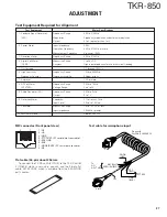
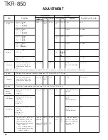
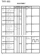
4. RX PLL lock
1) RX VCO A high
DVM
TX-RX
RX-CV
RX VCO TC350 1.50V
±
0.1V
voltage
CH : 11
K
(A/2)
(A3)
CH : 10
K2,K3,E
2) RX VCO A low
Check
8V or less
CH : 10
K
CH : 1
K2,K3,E
3) RX VCO B high
RX VCO TC351 1.50V
±
0.1V
CH : 3
K,K2
(A3)
CH : 11
K3,E
4) RX VCO B low
Check
8V or less
CH : 5
K
CH : 6
K2,K3,E
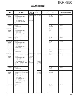
5. TX PLL lock
1) TX VCO high
TX-CV
TX VCO TC350 1.50V
±
0.1V
voltage
CH : 3
(A2)
K,K2,E
TC351
K3
2) TX VCO low
Check
8V or less
CH : 1
6. RX
1) Connect the frequency
f. counter
CN3
PC adj.
50Hz or less
frequency
counter to CN3, then
Test CH–44.85MHz
measure the frequency
CH : 2
Note :
RX frequency means the local frequency of the RX VCO. So its frequency is wanted frequency minus the IF frequency.
7. Setting
1) Remove 8 pin cable and the coaxial cable from CN16, and CN19 on TX-RX side.
8. TX
1) Connect the frequency
f. counter
TX-RX
CN19
PC adj.
50Hz or less
frequency
counter to CN19, then
(A/2)
measure the frequency
CH : 2
9. Setting
1) Insert 8 pin cable and the coaxial cable to CN16, and CN19 on TX-RX side.
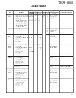
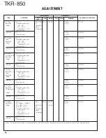
10. Maximum
1) Measure the RF power at
Power meter Rear
TX ANT
Final
VR1
Adjust the RF power
±
1W
power
TX ANT.
to 43W.
limitting
High CH
11. TX RF
1) Measure the RF power at
PC adj.
±
1W
high power
TX ANT.
40W
Low CH
(Factory-default)
2) Center CH
3) High CH
12. TX RF
1) Measure the power level at
PC adj.
±
1W
low power
TX ANT.
25W
Low CH
(Factory-default)
2) Center CH
3) High CH
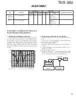
13. BPF
1) Connect the TG to RX ANT,
Tracking
Rear
RX ANT
TX-RX
L2
Center the frequency
then connect CN1 to the
generator
(A/2)
L4
you are using, then
spectrum analyzer input.
L5
adjust it to look like
Spectrum analyzer setting
Spectrum
TX-RX
CN1
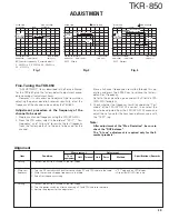
the wave Fig. 1.
Span : 50MHz
analyzer
(A/2)
(Page 39)
Scale : 10dB to 5dB div
Tracking generator setting
Output : –30dBm

