PRECAUTION FOR USE
1) CHECKING INPUT VOLTAGE
1) K e e p t h e permitted range of input v o l t a g e . Single
p h a s e , 1 0 0 / 1 2 0 / 2 0 0 / 2 2 0 / 2 4 0 V A C , ± 1 0 % ,
5 0 / 6 0 Hz
2) T h e a d a p t e d input v o l t a g e is indicated at t h e A C input
terminal o n t h e rear p a n e l .
3) W h e n c o n v e r t e d t h e line v o l t a g e , refer t o t h e s e c t i o n
of M A I N T E N A N C E .
2) POWER CORD CONNECTION
S o m e m o d e l s h a v e a c o n n e c t o r retainer o n t h e A C c o r d
c o n n e c t o r t o hold t h e c o r d f r o m slipping off.
For s a f e operation, be s u r e t h e retainer is l o c k e d .
3) OUTPUT CONNECTION
1) M a k e s u r e t h a t t h e rear-panel output terminals a n d
control terminals are c o n n e c t e d w i t h j u m p e r s a s
s h o w n F i g . 2 .
2) T h e output lines are floating. C o n n e c t either of t h e
front-panel output t e r m i n a l s t o G N D normally w i t h
short bar.
4) ENVIRONMENTAL CONDITIONS
1
1
K e e p t h e operating t e m p e r a t u r e range of 0 ° t o 4 0 ° C .
If t h e a m b i e n t t e m p e r a t u r e r i s e s e x c e s s i v e l y , t h e
d e v i c e ' s protection s y s t e m w o r k s a n d c u t s off p o w e r .
2) K e e p clear t h e ventilation o p e n i n g s (at s i d e s a n d bot-
t o m ) a n d t h e p a s s a g e of f a n air. Install a n y other
d e v i c e s more t h a n 3 0 c m apart f r o m t h o s e o p e n i n g s .
3 ) A v o i d t o install t h e p o w e r s u p p l y in a d u s t y p l a c e a n d
w h e r e t h e r e are m u c h c o r r o s i v e g a s e s .
4 ) A v o i d t o install s e n s i t i v e i n s t r u m e n t s o n a n d b e s i d e t h e
p o w e r s u p p l y .
1
F i g . 1
Output terminals of rear panel
Control terminals
Fig. 2
Содержание PD18-20
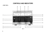
Страница 8: ... F R O N T P A N E L CONTROLS AND INDICATORS Fig 3 8 ...
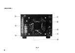
Страница 10: ... R E A R P A N E L Fig 4 10 ...
Страница 26: ...DIMENSIONS Fig 2 0 26 ...


