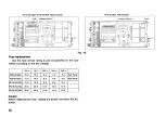
Connect of control terminals
Slave
Slave
Output connection
Master
Slave (1)
Slave
( 2 1
Load
E
0
= E
1
+ E
2
+ E
3
At negative ground
* Set the current controls of all slave units at maximum position.
11
H o w t o d e t e r m i n e e x t e r n a l r e s i s t a n c e
H
t
a n d R
2
(
F \
x
RF
- R s [kG] (Ri ^ 0 (kQ), E
2
^ —
^ 2
/ Rs
Ej [V]: Output voltage of master
E
2
[V]: Output voltage of slave ( J ) when master's output
voltage is
E
t
R
s
, Rt:
Slave ( f ) ' s constants depending on model.
PD-
8 - 2 0 / 2 0 D
8 - 3 0 / 3 0 D
1 8 - 2 0 / 2 0 D
1 8 - 3 0 / 3 0 D
3 5 - 2 0 / 2 0 D
Rs
IkO!
10
kO
10 kO
10
kO
10 kfi
10 kQ
Rf
CkQ)
8 kO
8
kO
18
kO
18
kQ
3 6 kfi
T o obtain R
2
, replace EJ and E
2
w i t h E
3
in the a b o v e equation.
N o w , m a s t e r unit c o n t r o l s s l a v e unit ® and s l a v e unit © c o n -
trols s l a v e unit © .
N o t e s :
111
T h e s e c o n n e c t i o n c o n d i t i o n s are not s a t i s f i e d on t h e
m o d e l s b e l o w 1 0 V in rated output. F o r details, c o n t a c t
t h e n e a r e s t a g e n t or our distributor.
(2) M a x i m u m v o l t a g e during s e r i e s operation d o e s not e x -
c e e d rating of t h e w i t h s t a n d v o l t a g e to g r o u n d . B e careful
about t h e p o w e r ratings of R
r
a n d R
2
a n d u s e o n e s h a v i n g
a g o o d t e m p e r a t u r e c h a r a c t e r i s t i c .
/ E,
\ 2
P o w e r rating [ W ] =
- —
x R
t
\ PJ + RS /
For remote s e n s i n g during s e r i e s operation, u s e t h e ( + S ) ter-
minal of t h e m a s t e r w
;
" * h e © s e n s o r or t h e ( — S ) terminal of
t h e last s l a v e w i t h t h e ^
s e n s o r
(refer to t h e s e c t i o n of remote
s e n s i n g ) .
Master
At positive ground
F i g . 1 2
Содержание PD18-20
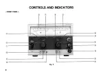
Страница 8: ... F R O N T P A N E L CONTROLS AND INDICATORS Fig 3 8 ...
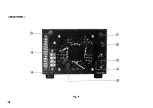
Страница 10: ... R E A R P A N E L Fig 4 10 ...
Страница 26: ...DIMENSIONS Fig 2 0 26 ...

