


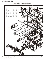


NXR-800H
105
■
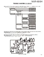
Traceability Procedure of IC34 (The RF control
MPU)
Confi rmation of Power Source Voltage
Test
Point Normal
Output
Voltage
IC16 (pin 5) 5VDC
IC329 (pin 4)
3.3VDC
Correct
condition
Confi rmation of Clock frequency
Test
Point Proper
Frequency
R195 14.7456MHz
(either end of R195 is OK)
Correct
condition
Confi rmation of Reset control
Test
Point Normal
Control
Voltage
IC303
(pin
1) 3.3VDC
Correct
condition
Parts other than IC34 are malfunctioning.
1-3. Hardware Traceability (Method 2)
The NXR-800H control circuit executes the following pro-
cedures when the system starts up.
1. An external DC 13.2V power source is applied to the
NXR-800H terminal.
2. The Modem control MPU (IC325) starts up.
3. The Modem control MPU (IC325) initiates all circuit
blocks.
4. The Main MPU (IC703) and the RF control MPU (IC34)
start up.
Confi rmation of IC16 (pin 5) output
Remove R201. If 5 VDC, IC34 is malfunctioning.
Confi rmation of IC329 (pin 4)
Remove R159. If 3.3 VDC, IC34 or IC17 may be
malfunctioning.
If the oscillation of 14.7456MHz cannot be con-
fi rmed:
X1 is malfunctioning or the circuit around X1 is mal-
functioning.
Clock oscillation amplitude is weak:
Drive circuit in IC34 is malfunctioning.
Remove R332 and confirm the voltage of the
pad on the opposite side of IC34:
If 3.3 VDC, IC34 is malfunctioning.
Abnormal
condition
Abnormal
condition
Abnormal
condition
5. The Main MPU (IC703) confi rms the operational status of
the Modem control MPU (IC325) and the RF control MPU
(IC34) by using 115.2kbps UART communications and
then the operation transfer commands will be exchanged
in order to integrate all hardware blocks.
The above steps 1 to 5 will be executed as follows.
TROUBLE SHOOTING
Содержание NXR-800H
Страница 180: ...1 E CN300 RX_IF_VN 168 ...


