


NXR-700
12
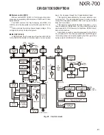
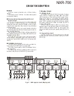
2-8. AVR circuit
IC104, IC603, IC704, IC705, IC706, IC807, IC808, IC809
and IC810 are AVR ICs.
Each circuit contains its own power regulator IC to main-
tain isolation between circuits.
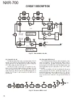
2-9. Other circuits
In addition, IC702 is an EEPROM. The transmitter ad-
justment data adjusted for each unit is written into the EE-
PROM. If the unit is installed in another set, it is not nec-
essary to adjust it again from the beginning, but only fi ne-
tuning is necessary for each unit.
The temperature sensor (IC804) monitors the tempera-
ture of the transmitter unit (X56-311 A/3).
The D/A converters (IC701 and IC802) converts the AGC
setting (D_PC) of the driver circuit and control voltage value
(PWR_CONT, PWR_PRT) of the Final Unit (X45-385 A/5).
The A/D converter (IC803) converts the transmitter unit
(X56-311 A/3) temperature, VCO & VCXO control voltage
(CVT, CVT-REF and CVT-MOD), Final Unit (X45-385 A/5)
PA current(PA_CURR), fan current (FAN_CURR), detection
voltage (FWD_PWR, RFL_PWR), etc.
The shift register (IC703) controls each part of the trans-
mitter unit (X56-311 A/3) based on serial data of the Control
Unit (X53-413).
CN801
VBATT
+13.2V
IC704
IC80
9
SW
Ripple
filter
IC807
IC706
IC705
IC603
IC104
IC808
8V #1
8V #2
8V
9
V
CN807
8V #2
OCXO
9
V’
8V #1
8V #1’
5V #1
5V #2
5V #3
3.3V
IC810
3V
Fig. 8 AVR circuit
3. Final unit
The RF final amplifier unit (X45-385 A/5) amplifies the
transmitter power to a specifi ed level.
This unit consists of the following circuits:
(1) Transmitter power module
(2) High pass fi lter
(3) Forward/Refl ect power detector circuit
(4) Antenna switch
(5) Harmonic fi lter circuit
(6) APC circuit
(7) High temperature detector circuit
(8) FAN action control circuit
(9) Current detector circuit
(10) AVR Circuit
(11) Other Circuits
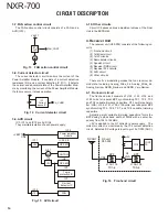
3-1. Transmitter power module
The power module IC10 uses power module RA60H1317
M1A to improve its effi ciency. The driver output of the trans-
mitter unit passes through an attenuator and enters the pow-
er module IC10 pin 1. Power module IC10 amplifi es the RF
power according to the voltage at the amplifi cation control
pin 2 (VGG) and outputs it through pin 4 (Pout).
RA60H1317M1A
a
Pin
b
VGG
c
VDD
d
Pout
Fig. 9 Transmitter power module
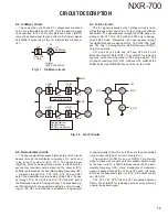
3-2. Low pass fi lter and High pass fi lter
The T type single stage low pass fi lter and high pass fi lter
prevents the Power Amplifi er Module from being broken by
static electricity.
CIRCUIT DESCRIPTION
Содержание NEXEDGE NXR-700
Страница 110: ...NXR 700 110 MEMO ...
Страница 119: ...NXR 700 117 MEMO ...
Страница 137: ...NXR 700 135 MEMO ...
Страница 138: ...NXR 700 136 MEMO ...
Страница 140: ...NXR 700 ...
Страница 171: ...1 E CN300 RX_IF_VN ...


