0P-1100B II DP-1100B II
4. TROUBLESHOOTING
PLAY STOP
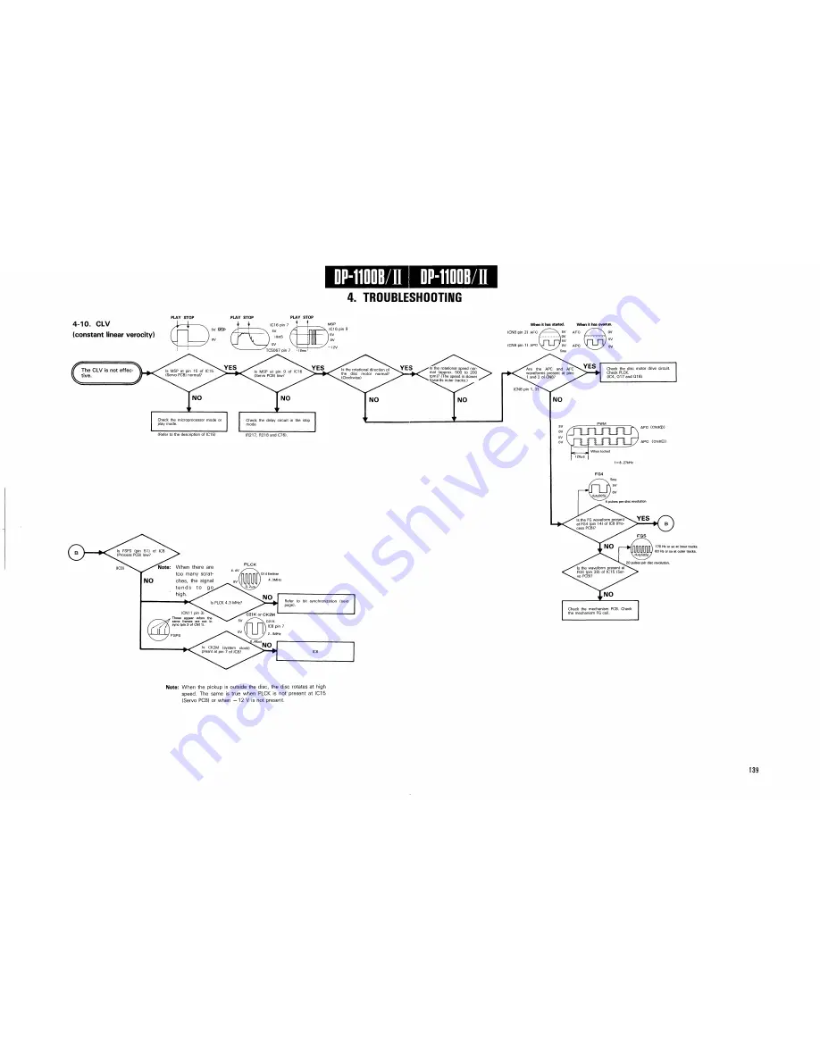
4-10. C L V
(constant linear verocity)
The C L V is not effec
tive.
When it has started.
(CN8 pin 2) A F C
When it has overrun.
A F C / \ OV
Check the disc motor drive circuit.
Check PLCK.
(IC4, Q 1 7 and Q18)
N O
Check the microprocessor mode or
play m o d e .
(Refer to the description of IC15)
N O
r
Check the delay circuit in the stop
mode
( R 2 1 7 , R 2 1 8 and C 7 6 ) .
Note: When there are
too many scrat-
N O ches, the signal
t e n d s t o g o
high.
• Is PLCK 4 . 3 MHz?
\ Q I 4 E m i t t e r
4 . 3 M H z
(CN11
p i n
3)
T h e s e appear w h e n t h e
s a m e f r a m e s are n o t i n
s y n c (pin 3 o f C N 1 1 ) .
1 7 0 Hz or s o a t inner t r a c k s .
6 0 Hz or so a t o u t e r t r a c k s .
Check the m e c h a n i s m PCB. Check
the mechanism FG coil.
Note: When the pickup is outside the disc, the disc rotates at high
speed. The same is true when PLCK is not present at IC15
(Servo PCB) or when - 1 2 V is not present.
I 3 9
Содержание DP-1100 B
Страница 3: ...D P 1 1 0 0 B II D P 1 1 0 0 B II I BLOCK DIAGRAM ...
Страница 32: ...D P 1 1 0 0 B II 1 CIRCUIT DESCRIPTION Disc Scratch Dust RFES D C O N D O C K Fig 1 2A 3 5 ...
Страница 112: ...2 IC OPERATION OF EACH CIRCUIT AND D P 1 1 0 0 B II PIN DESCRIPTION Fig 2 4 1 G 1 ...
Страница 117: ...DP 1100B II I OPERATION OF MAIN MICROPROCESSOR Fig 3 1D Q data reading flow chart ...
Страница 121: ...D P 1 1 0 Q B II OPERATION OF MAIN MICROPROCESSOR Fig 3 1 E Operation flow chart of dynamic search system ...


