DP-1100B II
4. TROUBLESHOOTING
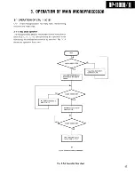
4-1 Checking flow chart of the start operation from the moment power is switched on until operation
is enabled. * Actual action taken by DP-1100B/II
Circuits a n d signal line w r i t t e n in p a r e n t h e s i s in t h e left c o l u m n is t h e place to be c h e c k e d .
( P O W E R oi\P)
The microprocessor
is reset.
1 r
The tray position is
detected.
r
The pickup
is detected.
position
(reset circuit)
(limit switch): S L T
(close or open): C L S , OPEN
* W h e n it is open, the tray is retract
ed and proceed to the next opera
tion.
(limit switch)
(SLT)
(P.U. motor circuit)
* W h e n the pickup is at the outer
tracks of the disc, it moves to the
innermost tracking position and
proceed to the next operation.
Laser diode goes on; focus search starts;
forward kick; the disc motor operates in
stantaneously.
A b s e n c e or pre
sence of the disc is
detected.
(LDC, focus search (FSRCH), PUFB, F G S ,
inverter buffer output MSP)
(kick motor circuit)
* W h e n there is no disc, the motor
rotates in the forward direction momen
tarily (clockwise), then in reverse (ap
prox. 2 s e c ) .
(Focus error, DOK)
(Focus servo)
* W h e n there is no disc, the laser diode
goes out, then focus search stops and
fluorescent indication " D I S C " goes
out.
DISC motor start
RFOK is detected.
Focus servo on
Focus search stop
Tracking servo on
(IC15, MSP, A F C , CLV)
(S1, S 2 , E F M , RFOK)
(Focus servo, A G C )
(Slice level)
(FOK)
* T max. is detected.
(Focus servo)
(FOKG, K G C , T E : Tracking error)
(Tracking servo) (Dropout control)
Rising edge of 5 V power
Reset
POWER ON-
FL display
Flashes-
T R A C K N O .
T I M E
• ( . D I S C )
1
Pull out the tray, then switch on the power without
inserting the disc.
1
The tray is retracted.
1
The pickup moves slightly backwards, and the laser diode is
reflected in pale red on the pickup lens.
The pickup moves 1 mm or so vertically.
The disc motor momentarily rotates in the forward direction, then
reverses for about 2 sec. before stopping. The fluorescent display
DISC goes out.
Pull out the tray, then insert the disc.
The tray is closed.
1
The disc rotates momentarily, then resumes normal revolution.
(If it does not rotate, check DOK, and A F C . )
With the sound of the rotating disk, the EFM presents jitterless
waveform. ( F O C U S , tracking servo on)
* If there is no sound and the E F M , RFOK, or EFM waveform is jit
tered, check-the tracking circuit.
1 3 1
Содержание DP-1100 B
Страница 3: ...D P 1 1 0 0 B II D P 1 1 0 0 B II I BLOCK DIAGRAM ...
Страница 32: ...D P 1 1 0 0 B II 1 CIRCUIT DESCRIPTION Disc Scratch Dust RFES D C O N D O C K Fig 1 2A 3 5 ...
Страница 112: ...2 IC OPERATION OF EACH CIRCUIT AND D P 1 1 0 0 B II PIN DESCRIPTION Fig 2 4 1 G 1 ...
Страница 117: ...DP 1100B II I OPERATION OF MAIN MICROPROCESSOR Fig 3 1D Q data reading flow chart ...
Страница 121: ...D P 1 1 0 Q B II OPERATION OF MAIN MICROPROCESSOR Fig 3 1 E Operation flow chart of dynamic search system ...


