background image

[ E 2 S 1  0 ]

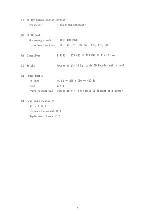
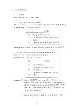
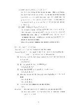
 VCR LOCATE Command 

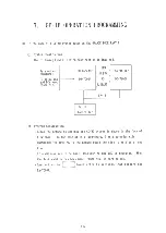
(Function) Transports tape to specified time-defined position. 

(Command format)

  E 2 S 1 0

 !  H I

0

H I M I

0

M I S I

0

S I F I

0

F I $ / 

H i o

 ~F

i

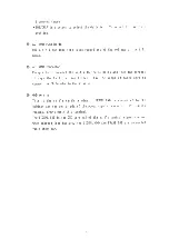
  i n d i c a t e s SMPTE time, minutes, seconds, frame 

number  i n tens and single  d i g i t s . 

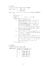
(Note) Before using  t h i s command, set the subcode generation mode to STOP 

mode and the VCR to PLAY mode. 

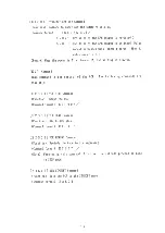
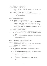
[ E 6 ] Command 

This group of commands  i s used as the data of the subcode generation. 

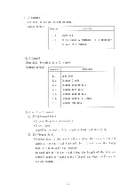
[ E 6 S 0  0 ]

 Disc Type Setting 

(Function) By setting the disc type, generation of the LEAD-IN portion' s 

subcode takes place  i n accordance with the disc type. 

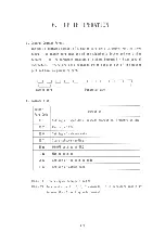
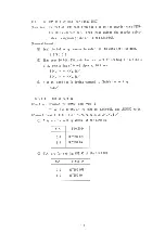
(Command format)  E 6 S 0 0

  ! N i N

2

$ / 

N,N

DISC TYPE 

0 0 

0 1 

0 2 

CD-DA, CD-ROM 

Undefined 

Undefined 

(Remark) When the power  i s  f i r s t turned ON, the  s e t t i n g  i s NiN

2

=00. 

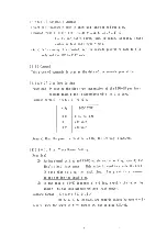
[ E 6

 S

 0  1 ]

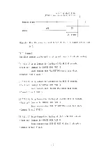
  F i r s t Track Number Setting 

(Function) 

0 During normal cutting and CD-WO uninterrupted  w r i t i n g , specify the 

disc' s  f i r s t track number. This value  i s used to create the LEAD-

IN data when  s e t t i n g the  t r a c k time. Carry out  t h i s command 

before setting the track time. 

(D In the case of CD-WO incremental  w r i t ing,  s p e c i f y the value by 

adding 1 to the last already written track number. 

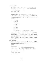
(Command format)  E 6 S 0 1

  ! N i N

2

$ / 

01 ^ Ni N

2

 ^ 99 (NiN

2

 are numeric values between  0 - 9 ) 

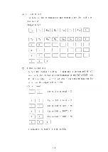
(Remark) When the power  i s  f i r s t turned ON, the  s e t t i n g N1N2 =01. 

1 3 

Содержание DA-7000A

Страница 1: ...D A 7 0 0 0 A CD ENCODER INSTRUCTION MANUAL K E N W O O D C O R P O R A T I O N ...

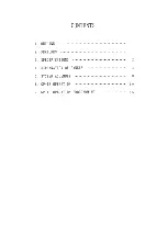
Страница 2: ...CONTENTS 1 OUTLINE 1 2 FEATURES 1 3 SPECIFICATIONS 2 4 EXPLANATION OF PANELS 4 5 SYSTEM ASSEMBLY 8 6 GP IB OPERATION 1 0 7 GP IB OPERATION PROGRAMMING 2 5 ...

Страница 3: ... construct ion of a CD WO system through combination with a C D W O Writer DD 7200A 2 The control functions necessary for the encoder including generation of the subcode are a l l control led through the GP IB System incorporation i s facilitated by possible control of the VCR and DAT through the GP IB 3 Through a p p l i c a t ion of L S I i n the CD Encoder c i r c u i t r y has been simplified ...

Страница 4: ...ector Canon connector External synchronization clock 44 1 kHz 50 ohms TTL level output BNC R use 5 SDIF Data Input W O R D SYNC 75 ohms TTL level output BNC R use DEC CHI 75 ohms TTL level input BNC R use DEC CH2 75 ohms TTL level input BNC R use 6 Parallel Data Input Data format 8 bit units positive logic 2 s complements Input level TTL level PULL UP 330 ohm PULL DOWN 390 ohm Connector 50 pin min...

Страница 5: ...SHI AH1 16 L3 SRI DC0 DTO CO 10 Dimensions EIA133 133 H x 428 W x 415 D m m 11 Weight Approximately 10 kg basic CD Encoder unit alone 12 Power Supply Voltage AC 85 250 V 50 440 Hz Fuse 2 5 A Power consumption Approximately 10 W basic CD Encoder unit alone 13 Supplied Accessories AC cord x 1 Instruction manual x 1 Replacement fuses x 2 ...

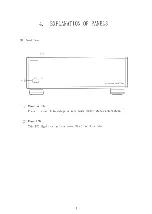
Страница 6: ...4 EXPLANATION OF PANELS 1 Front Panel Power switch Press this switch to change between power ON OFF status alternately Power LED This LED lights to indicate power ON of the CD Encoder 4 ...

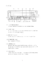
Страница 7: ...terminal 44 1 KHz clock output to PCM processor for external synchronization D CH1 DEC CH2 terminal Input terminals for SDIF data N EFM OUT terminal EFM output that does not pass through the symmetry adjustment circuitry In the case of a CD WO system connect t h i s terminal with the CD Writer s N EFM IN terminal EFM OUT terminal Output terminal for the EFM signal In the case of a C D W O system c...

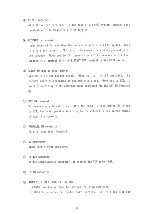
Страница 8: ... set to the INT pos i t ion the encoder operates according to the b u i l t i n clock When set to EXT i t operates according to the external clock connected v i a the EXT IN terminal EXT IN terminal To connect an external clock When the CLOCK INT EXT switch i s set to EXT the unit operates according to the external clock signal coming through this connector PARALLEL IN connector Parallel data inpu...

Страница 9: ... the current through the bui 1 t i n 1 ine f i l t e r Use the suppl ied power cord to connect the CD Encoder to the AC mains GND terminal This i s the u n i t s earth terminal FRAME GND i s connected to the cabinet and the center pin of the power supply connector For safety reasons always earth this terminal The SIGNAL GND i s the GND terminal of the unit s control signal system When shipped from...

Страница 10: ...rfaces SDIF For PCM processor SONY PCM 1610 PCM 1630 etc D AES EBU Digital Audio Interface DAT for professional use FOSTEX D 20 etc D Parallel Input Since a 44 1 kHz and 88 2 kHz timing signal i s output data synchronized with these frequencies can be input 2 Connect ion to Recording Equipment In the case of a C D W O system conforming to the ORANGE BOOK PART I I connect the C D W O Writer DD 7200...

Страница 11: ... O system u t i l i z i n g U matic VCR VCR SONY DMR 4000 PCM PROCESSOR SONY PCM 1630 W O R D SYNC CD ENCODER DA 7000A EFM N EFM FS E START C D W O WRITER DD 7200A RS 422 7fT GP IB PC PC 9801 9 DEC CHI DEC CH2 ...

Страница 12: ... of the master part and have no parameter part Master Part Code Operat ion E 1 Setting of input data subcode generation symmetry switch E 2 Control of VCR E 6 Setting of subcode data E 7 Start subcode sending H n ON OFF setting of SRQ I n Muting setting J n Setting of the sett ing mode L n Setting of output data Note 1 n i s a cipher between 0 and 9 Note 2 To execute the E l 2 6 7 commands i t i s...

Страница 13: ...N2 00 SDIF E 1 S 0 1 Command for setting the subcode generation method Function Sets the way the subcode i s generated Command format E 1 S 0 1 N i N 2 NiN2 FUNCTION 0 0 FREE RUNNING mode In the case of normal cutting 0 1 START STOP mode In the case of ORANGE BOOK PART I I 0 2 STOP mode Remarks When the START STOP mode i s specified the sending of the subcode can be control led by the input signal...

Страница 14: ...g i s NiN2 00 E 2 Command This command i s for control of the VCR The fo1 lowing commands are available E 2 S 0 0 VCR STOP Command Function Stops the VCR Command format E 2 S 0 0 E 2 S 0 1 VCR PLAY Command Function Starts VCR play Command format E 2 S 0 1 E 2 S 0 2 VCR REWIND Command Function Rewinds the tape to i t s beginning Command format E 2 S 0 2 Note When using this command f i r s t set th...

Страница 15: ...ce in accordance with the disc type Command format E 6 S 0 0 N i N 2 N N2 DISC TYPE 0 0 0 1 0 2 CD DA CD ROM Undefined Undefined Remark When the power i s f i r s t turned ON the setting i s NiN2 00 E 6 S 0 1 First Track Number Setting Function 0 During normal cutting and C D W O uninterrupted writing specify the disc s f i r s t track number This value i s used to create the LEAD IN data when set...

Страница 16: ... program area s starting time 00 M 00 S 00 F In the case of C D W O incremental writing the command i s used to specify the starting time for the additional writing 2 M START S 7 M i o M i S i o S i F 1 0 F i This command i s used to specify the time when the melody or data i n the case of CD ROM etc should actual ly s t a r t inside the track In the case of the disc s f i r s t traci i f t h i s ...

Страница 17: ...he ending time of the last melody or data to be added When receiving this command the encoder terminates input E 6 S 0 5 Control Bit Setting Function Used to set the control bit for each track Command format B3 B 0 signifies the value 0 or 1 B3 4 2 CHANNEL B2 DATA bit Bi COPY bit and B0 EMPHASIS b i t I n i t a l l y send the following command to enter the contro1 b i t setting mode E 6 S 0 5 Set ...

Страница 18: ...e previously set START TIME OF LEAD IN and the part it ion number sett ing Command format E 6 S 1 1 N i N 2 00 NiN2 99 NiN2 are numeric values between 0 9 Remarks Previous to this setting the START TIME OF LEAD IN should be set When carrying out FINALIZING of the disc the PCA writing time should be NiN2 00 E 6 S 1 2 PMA Data Setting For INCREMENTAL WRITING Function Command for ORANGE BOOK PART I I...

Страница 19: ...data for one track by sending a t a time 4 bits consisting of 0 9 ciphers 20 times S N N 2 0 S N i N 2 0 D Finally send the following command to finish the sett ing S E 6 S 1 4 MUTING Setting Function Command for ORANGE BOOK PART I I To set the MUTING of the LEAD IN LEAD OUT and LINKING parts Command format E 6 S 1 4 I N i N s N s N a N z N s S NiN2 are for setting MUTING of the LEAD IN NiN2 FUNCT...

Страница 20: ...at the sub code frame part indicated by the x x 0 9 Recording start frame j ATIME frame specified by P START Subcode frame MUTING OFF O N X l frame N7 N8 are for setting the MUTING taking place at the location where writing stops in the case of INCREMENTAL WRITING N7 N8 FUNCTION 0 0 1 x MUTING OFF MUTING takes places only at the sub code frame part indicated by the x x 1 9 1 8 ...

Страница 21: ...d take place Command format E7S10 E 7 S 1 1 Setup Command for Sending of PMA WRITING subcode Function Command for ORANGE BOOK PART I I Sends subcode when PMA WRITING should take place Command format E7S11 E 7 S 1 2 Setup Command for Sending of LEAD OUT WRITING subcode Function Command for ORANGE BOOK PART I I Sends subcode when LEAD OUT WRITING should take place Command format E7S12 E 7 S 1 3 Setu...

Страница 22: ...bcode Function Command for ORANGE BOOK PART I I Sends the subcode when INCREMENTAL WRITING should take place Command format E7S15 E 7 S 1 6 Setup Command for Sending of INCREMENTAL WRITING With LEAD OUT Subcode Function Command for ORANGE BOOK PART I I Sends the subcode when INCREMENTAL WRITING should take place When using t h i s command sending of the LEAD OUT area subcode begins when sending of...

Страница 23: ...signal at the H level 5 0 When the execution of the VCR control command has been completed normally 5 1 When e x e c u t i o n i s i n t e r r u p t e d due to occurrence of transmission error during VCR control command execution 5 2 When the tape cannot be transported to the specified time defined position during execution of the VCR locate command In this case give the locate command several tim...

Страница 24: ...uts lead in data L 6 Outputs control bit data L 7 Outputs PMA data Action of each command D L2 Q Command Data Outputs the generated subcode Q Output format Headed by the control bit output is 4 bit unit HEX system D L3 Program Data Program data i s the result calculated on the basis of the set value of the set track time and the information on the change point of the actually sent subcode In addit...

Страница 25: ...es 1 frame For the meaning of FO F5 refer to the sect ion on TRACK TIME SETTING COMMAND F6 i s when the P code i s set 00 i s the code that comes after P START and M STOP However i t becomes the length 1 frame of the i n t e r v a l between melodies The data ends with END L4 Mark Data Mark data i s identical to the specified track time The time change point code i s the same as in the case of L3 T...

Страница 26: ...its corresponding to the TOC s POINT AO Al A2 are output A t o t a l of 99 3 102 sets of data can be output and the output ends with END Output format H indicates the control s 4 bit as HEX 2 4 T T2 Mio Mi S 1 o Si Fio Fi Ti T2 Mi o Mi S 1 0 Si Pi 0 Fi A 0 A 1 A 2 E N D H 0 Control bit of track 01 H 0 Control b i t of track 99 H 0 Control bit of POINT AO H 0 Control bit of POINT Al H 0 Control bit...

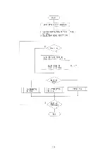
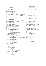
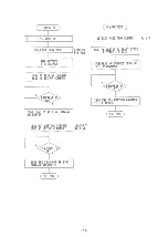
Страница 27: ...CD Writer DD 7200A GP IB GP IB Controller Program Construct ion Below the method to control the C D W O system i s shown in the from of flow chart In the case of this flow chart 3 writing modes exist UNINTERRUPTED WRITING i s the method where the disc i s written at one time If additions are to be made INCREMENTAL WRITING i s repeated When the last addition has been made FINALIZING i s carried out...

Страница 28: ...BCODE GENERATION METHOD SETTING START STOP MODE SELECTION Note 1 INCREMENTAL WRITING Note 2 2 6 N Y New disc Read the new special function code from disc START TIME OF LEAD IN SETTING UNINTERRUPTED WRITING FINALIZING WRITING COMPLETED N Y END ...

Страница 29: ... M M A N D PMA writing UNINTERRUPTED WRITING SUBCODE SETTING SET UP C O M M A N D 2 7 PCA WRITING PCA WRITING UNINTERRUPTED WRITING SETTING FIRST TRACK NUMBER INCREMENTAL WRITING SETTING TRACK TIME SETTING CONTROL BIT SETTING FIRST TRACK NUMBER SETTING TRACK TIME SETTING CONTROL BIT N Y PREPARATION OK Note 4 N SET THE WRITER TO READY STATE E START L level PREPARATION OK Y SEND UNINTERRUPTED WRITIN...

Страница 30: ...EPARATION J K 2 8 FINALIZING PCA WRITING READ PMA FROM DISC SET THE WRITER TO READY STATE E START L level Note 5 N Y SEND THE PCA WRITING C O M M A N D TO THE WRITER SUB END PREPARATION OK 1 N SEND LEAD IN WRITING C O M M A N D TO WRITER LEAD OUT WRITING SUBCODE SENDING SET UP C O M M A N D LEAD OUT Writing SEND THE LEAD OUT WRITING C O M M A N D TO WRITER PREPARATION JDK N SUB END ...

Страница 31: ...de sending set up command the E START signal must be set to the L level I f the writer detects the writing starting position set E START to H level Thus the DA 7000A starts sending the subcode Note 4 The DA 7000A receives the subcode sending setup command completes the internal processing and displays SRQ when the subcode sending setup can be done Note 5 Set the partition number to 00 when FINALIZ...

Страница 32: ...A product of KENWOOD CORPORATION 1 7 5 2 c h o m e S h i b u y a Sh i b u y a k u T o k y o 150 J a p a n ...

Отзывы: