2. Count the number of cycles of waveform between a
chosen set of vertical graduation lines.
Using the horizontal distance between the vertical lines
used above and the S W E E P TIME/DIV, the time span
may
be calculated. Multiply the reciprocal of this value
by the number of cycles present in the given time span.
If " x 10 M A G " is used multiply this further by 10.
Note that errors will occur for displays having only a few
cycles.
Using the formula:
# of cycles x " x 10 M A G " value
Freq=
Horizontal distance (div) x S W E E P TIME/DIV setting
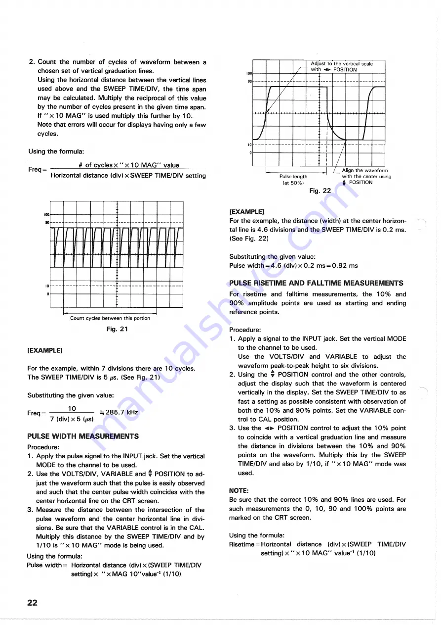
Count cycles between this portion
[EXAMPLE]
For the example, within 7 divisions there are 10 cycles.
The S W E E P TIME/DIV is 5 jis. (See Fig. 21)
Substituting the given value:
Freq=
—
= 2 8 5 . 7 kHz
7 (div) x 5
{(is)
PULSE WIDTH MEASUREMENTS
Procedure:
1. Apply the pulse signal to the INPUT jack. Set the vertical
MODE to the channel to be used.
2. Use the VOLTS/DIV, VARIABLE and
w
POSITION to ad-
just the waveform such that the pulse is easily observed
and such that the center pulse width coincides with the
center horizontal line on the C R T screen.
3. Measure the distance between the intersection of the
pulse waveform and the center horizontal line in divi-
sions. Be sure that the VARIABLE control is in the C A L .
Multiply this distance by the S W E E P TIME/DIV and by
1/10 is " x 10 M A G " mode is being used.
Using the formula:
Pulse width = Horizontal distance (div) x (SWEEP TIME/DIV
setting) x " x MAG 10"value"
1
(1/10)
Adjust to the vertical scale
with POSITION
[EXAMPLE]
For the example, the distance (width) at the center horizon-
tal line is 4.6 divisions and the SWEEP TIME/DIV is 0.2 ms.
(See Fig. 22)
Substituting the given value:
Pulse width = 4.6 (div) x 0.2 ms = 0.92 ms
PULSE RISETIME AND FALLTIME MEASUREMENTS
For risetime and falltime measurements, the 1 0 % and
9 0 % amplitude points are used as starting and ending
reference points.
Procedure:
1. Apply a signal to the INPUT jack. Set the vertical MODE
to the channel to be used.
Use the VOLTS/DIV and VARIABLE to adjust the
waveform peak-to-peak height to six divisions.
2. Using the • POSITION control and the other controls,
adjust the display such that the waveform is centered
vertically in the display. Set the SWEEP TIME/DIV to as
fast a setting as possible consistent with observation of
both the 1 0 % and 9 0 % points. Set the VARIABLE con-
trol to C A L position.
3. Use the POSITION control to adjust the 1 0 % point
to coincide with a vertical graduation line and measure
the distance in divisions between the 1 0 % and 9 0 %
points on the waveform. Multiply this by the SWEEP
TIME/DIV and also by 1/10, if " x 10 M A G " mode was
used.
NOTE:
Be sure that the correct 1 0 % and 9 0 % lines are used. For
such measurements the 0, 10, 9 0 and 1 0 0 % points are
marked on the C R T screen.
Using the formula:
Risetime = Horizontal distance (div) x (SWEEP TIME/DIV
setting) x " x 10 M A G " value"
1
(1/10)
2 2
Pulse length
(at 5 0 % )
Align the waveform
with the center using
* POSITION
Fig. 2 2
Fig. 21
Содержание CS-1045
Страница 34: ...MEMO 3 4 ...


