


Operating Instructions BA 77 600..A00 // Last updated: 13/03/2020 // Page 8 of 33
3. Installation
3.1 Mechanical installation
The hub (17) must be slipped onto a shaft provided with a feather key to DIN 6885,
sheet 1. The hub must be axially secured (by means of a shaft collar, circlip or the like).
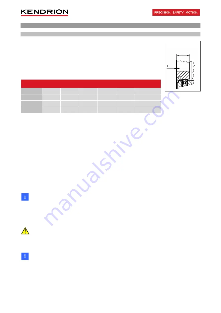
Make sure that the front face of the hub (17) is at the same height as the front face of
the flange (11). The friction disc (5) must be slipped onto the hub (17) with the complete
brake assembly and centred using centring diameter d
2
(see Fig. 6/1 and Classic Line
specification sheet) of the flange (11). Make sure that the friction disc (5) can be easily
moved along the hub (17).
Size
10
11
13
16
19
24
L [mm]
20,5
20,5
24
26,5
30
45
L
1
[mm]
0-0.8
0-0.8
0-1
0-1
0-1
0-1.2
M
A
[Nm]
5.5
5.5
5.5
9.5
9.5
22
M
AZ
[Nm]
1.5
1.5
3
5
5
11
Table 8/1: Hub dimensions (17); tightening torques of fixing screws (22)
and machine screws (13)
Check that the fixing surface (18) meets the following requirements before installing the brake:
•
Axial runout relative to the shaft <0.1mm (measuring radius = reference diameter)
•
Surface roughness max. R
z
16
•
Surface hardness min. 100HB
•
Material: steel, aluminium, cast iron – with excellent thermal conductivity
•
Absence of oil and grease
•
Permitted mismatch of centring diameter (fixing surface (18)) relative to shaft <0.2mm
The spring-applied single-disc brake must be screwed to the fixing surface (18) by tightening the fixing screws
(22) to the M
A
tightening torques specified in Table 8/1. The factory-adjusted rated air gap 's' cannot be
changed.
Note!
If the friction disc (5) and/or hub (13) are equipped with rubber buffers for noise reduction, the buffers must be
slightly greased before installation to reduce fitting forces during brake mounting. Check that the friction disc
(5) can be easily moved along the hub (13) by hand. The fitted components (especially the friction surfaces)
must be free from grease.
Attention!
The M
A
tightening torque specified for the fixing screws (22) must be strictly observed. The screws (22) must
be tightened evenly in diametrically opposite sequence.
Note!
The centring diameter d
7
(see Fig. 6/1) is factory-aligned relative to the centring diameter d
2
on the flange (11)
with a maximum 0.2mm radial runout. This enables easy attachment of a tachometer generator to the solenoid
housing (1.1).
Hub position
Содержание 7760016A00-0004
Страница 33: ......


