background image


K4100714000001-00 / 05.2017 


Assembly 

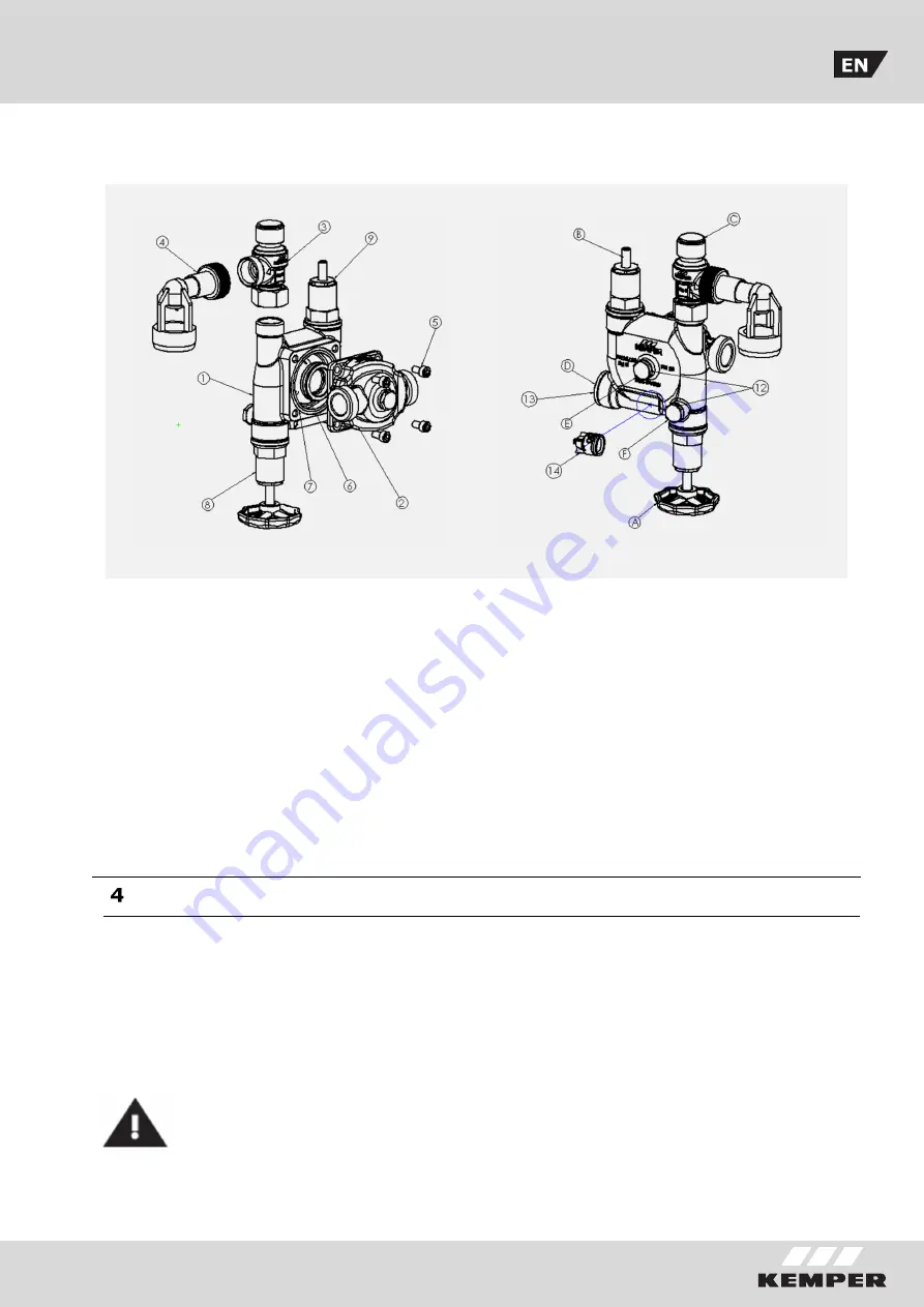
see Scope of delivery pages 2/3 Accessories | Spare parts list 


Mount basic module (2) in place by means 
of hexagon socket head cap screws M 6 x 
12 (5). After pressure testing (see 5. Initial 
system  checkout),  screw  the  diaphram-
type safety valve (3) onto the safety group 
housing  and  tighten  firmly.  For  pressure 
testing  purposes,  the  connection  for  the 
diaphragm-type safety valve can be closed 
off with a cap with an R ¾“ female thread). 
The  telescopic  drainage  funnel  (4)  is 
attached  to  the  safety  valve  and  aligned 
vertically  downward.  The  drainage  funnel 

must be rigidly connected to the blow-down 
piping. According to DIN 4753  Part 1, the 
blow-down piping may have a maximum of 
2  bends  and  be  a  maximum  of  2  m  in 
length. If reasons dictate the use of more 
bends or a greater length, then the entire 
blow-down piping must be dimensioned to 
have  the  next  higher  nominal  size.  More 
than 3 bends and a length of over 4 m are 
not  permissible.  The  blow-down  piping 
must  normally  be  installed  in  slanting 
position.


Initial system checkout 


In  the  as-delivered  condition  the  main 
isolating  valve  (A)  and  the  maintenance 
valve (B) are fully opened. It must first of 
all be ensured that the upstream piping has 
been adequately flushed through. The main 
isolating valve and the maintenance valve 
must  then  be  opened  successively.  Once 

the pressure in the system has stabilized, 
the  seal  cap  of  the  safety  valve  (C),  the 
backflow preventer test connection (F) and 
the pressure gauge connection (E) must be 
opened  for  a  short  time  in  order  to 
eliminate any air pockets.


The safety valve outlet must not be 
closed  off.  In  order  to  subject  the 
safety  group  to  pressure  testing, 
the safety  valve must be removed 
from the  safety  group  and  plugs  

used  to  seal  off  the  safety  group.  The 
pressure testing is performed at 1.5 times 
the working pressure to DIN 1988-2


Содержание 714 00 001

Страница 1: ...l Basismodul Fig 714 0G mit Sicherheitsventil 0 6 MPa 6 bar Fig 715 0G mit Sicherheitsventil 0 8 MPa 8 bar Fig 716 0G mit Sicherheitsventil 1 0 MPa 10 bar Varianten Funktionsmodul ohne Basismodul Fig...

Страница 2: ...itung an geschlossenen Trink wassererw rmern TWE Mit der Sicherheitsgruppe k nnen geschlossene Trinkwassererw rmer bis 150 kW Heizleistung 200 bis 1000 Liter Inhalt nach DIN 1988 Teil 2 sowie DIN 4753...

Страница 3: ...en J81097140000100 14 RV Patrone DN 20 P41001580002000 15 Drucksensor 1380000600 Zubeh r A Hauptabsperrung B Wartungsabsperrung C Sicherheitsventil D RV Wartungsbohrung E Manometeranschluss F RV Pr fa...

Страница 4: ...20 6 27 5 27 5 max Durchfluss wert kvs m h 4 5 4 5 4 5 Gewicht kg 2 10 2 84 2 88 Nennvolumen Ventilgr e min DN Heizleistung max kW 200 15 R Rp 75 200 1000 20 R Rp 150 1000 5000 25 R Rp 1 250 Die Ausle...

Страница 5: ...Planung des Warmwassersystems zu erfolgen Daf r sind sowohl der Warmwasserbedarf der Einzelverbraucher als auch der gleichzeitig ben tigte Warmwasserbedarf aller Verbraucher zu ermitteln Anschlie end...

Страница 6: ...Modul S wird zusammen mit dem KEMPER Basis Modul und den Verschraubungen in die Kaltwasserzuleitung zum TWE eingebaut Durchflussrichtung beachten Vor dem Einbau sind die Zuleitungen gut durchzusp len...

Страница 7: ...die gesamte Abblaseleitung eine Nennweite gr er ausgef hrt sein Mehr als 3 B gen sowie eine L nge ber 4 m sind unzul ssig Dabei muss die Abblaseleitung mit Gef lle verlegt werden Erstinbetriebnahme I...

Страница 8: ...erhalb des h chstm glichen erreichbaren Wasserspiegels des Trinkwassererw rmers liegen 6 1 Wartung des R ckflussverhinderers Die Rohrleitung in Fliessrichtung vor dem RV durch die Hauptabsperrung A ve...

Страница 9: ...ule incl basic module Fig 714 0G with safety valve 0 6 MPa 6 bar Fig 715 0G with safety valve 0 8 MPa 8 bar Fig 716 0G with safety valve 1 0 MPa 10 bar Variants Function module only without basic modu...

Страница 10: ...lf contained drinking water heaters against excess pressure The safety group is suitable for safeguarding self contained drinking water heaters with ratings up to150 kW and capacities 200 and 1000 lit...

Страница 11: ...0002000 15 Pressure sensor 1380000600 Accessories A Main isolating valve B Maintenance valve C Safety valve D Backflow preventer maintenance hole E Pressure gauge connection F Backflow preventer test...

Страница 12: ...7 T3 mm 20 6 27 5 27 5 max flow rate kvs m h 4 5 4 5 4 5 weight kg 2 10 2 84 2 88 Nominal volume Valve size min DN Heater rating max kW 200 15 R Rp 75 200 1000 20 R Rp 150 1000 5000 25 R Rp 1 250 The...

Страница 13: ...umers It is then possible to calculate the size of the drinking water heater the water heating period operationally permissible in the tank and the amount of hot water extracted m h in order to arrive...

Страница 14: ...d together with the KEMPER basic module and the fittings in the piping conducting the cold water to the drinking water heater heed direction of flow The piping must be thoroughly flushed through befor...

Страница 15: ...down piping must be dimensioned to have the next higher nominal size More than 3 bends and a length of over 4 m are not permissible The blow down piping must normally be installed in slanting positio...

Страница 16: ...e the highest attainable water level of the drinking water heater 6 1 Maintenance of the backflow preventer Close off the piping in flow direction upstream of the backflow preventer by means of the ma...

Отзывы: