Brownout Or Blackout
If a blackout or brownout occurs the T20 timer will not retain memory of where in
its run or stop cycles it may have been. When power resumes, the T20 will reboot
and resume running. A manual reboot can be done at any time by pressing the
timer’s reset button.
The T20 timer derives low voltage for its opera-
tion from a non-isolated reactance power sup-
ply (not through an isolated transformer). All
external devices connected to the T20 must be
earthed and must be regarded as operating at
full mains potential. For all mains voltage ap-
plications we recommend the supply to the T20
be isolated by an RCD that has a maximum trip
current of 30mA.
WARNING
Cables
The T20 timer has 3 X M20 cable glands. As supplied the cable glands are
blanked off. To use the glands first punch out the blanking barriers using a suit-
able punch. The cable glands can accept cable from 7 to 9mm diameter. See
attached sketch for assembling the cable gland components. The timer is sup-
plied with a set of steel crimp rings. The crimp rings are to provide strain relief for
the timers cables. To use the crimps, place one on the cable approximately 4mm
below the end to the cable’s outer sheathing. Crimp the two ears of the ring flat
using bull nosed pliers. Pull the cable back through the cable gland until the crimp
ring’s ears are fully engaged in the two slots in the gland housing.
6
Содержание T20
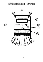
Страница 17: ...T20 Controls and Terminals 15...
Страница 34: ......


