43
Figure 19
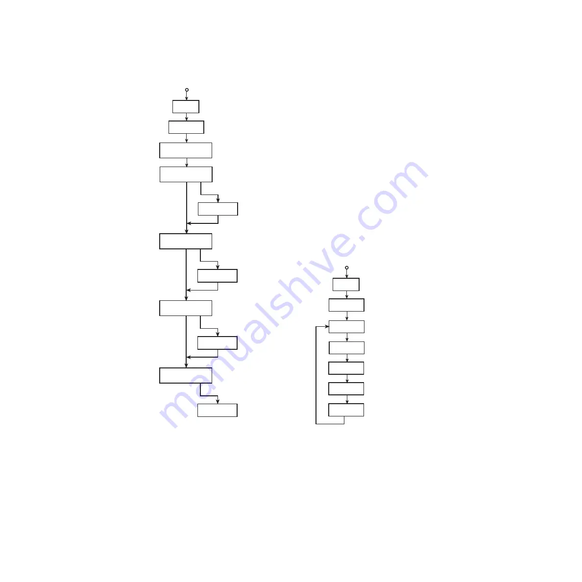
CARD menu paths for Model 7707
CONFIG
SLOTx: 7707 Select slot that has the
Model 7707; x is the slot number
Press SHIFT and
then CARD
Select CARD: CONFIG
Analog Input
Channels
View closed analog
input channels; 1-10,
A) Configure module
B) View channels
CHAN x11: IN
IN
OUT
DIGOUT1: 255
CHAN x12: IN
IN
OUT
DIGOUT2: 255
CHAN x13: IN
IN
OUT
DIGOUT3: 255
CHAN x14: IN
OUT
DIGOUT4: 255
VIEW
SLOTx: 7707
Press SHIFT and
then CARD
Select CARD: VIEW
View Digital Input or Output
Value for I/O Channel 11:
000 to 255 (ASCII)
x11:IN 000
View Digital Input or Output
Value for I/O Channel 12:
000 to 255 (ASCII)
View Digital Input or Output
Value for I/O Channel 13:
000 to 255 (ASCII)
View Digital Input or Output
Value for I/O Channel 14:
000 to 255 (ASCII)
Set Digital Output 1:
000 to 255 (ASCII)
FORMAT: ASC
Select data format; ASC (ASCII),
HEX (hexadecimal), BIN (binary)
Set Digital I/O Ch 11 as IN (input)
or OUT (output)
Set Digital I/O Ch 12 as IN (input)
or OUT (output)
Set Digital I/O Ch 13 as IN (input)
or OUT (output)
Set Digital I/O Ch 14 as IN (input)
or OUT (output)
Set Digital Output 2:
000 to 255 (ASCII)
Set Digital Output 3:
000 to 255 (ASCII)
Set Digital Output 4:
000 to 255 (ASCII)
Select slot that has the
Model 7707; x is the slot number
x12:IN 000
x13:IN 000
x14:IN 000
Factory and *RST default settings are
shown in these flowcharts.
NOTE:
Содержание 7707
Страница 55: ...52 Specifications 7707 Multiplexer Digital I O Module...
Страница 58: ......


