
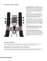
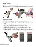


Line 1 RPM (Cadence) -
The RPM display counts
the cyclists revolutions per minute on one crank arm.
RPM is known in the cycling world as Cadence and
roughly is the speed at which the cyclist is pedalling.
At above 140 RPM the word “STOP” will appear to
indicate that the cyclist is pedalling faster than he or
she needs to be.
Line 2 Power -
The power output is displayed in
Watts (currently generating) and Kilocalories (total
value for the ride). The computer toggles back and
forth between Watts (displayed for eight seconds)
and Kilocalories (displayed for two seconds).
Line 3 Heart Rate -
If there is no heart rate signal, a
steady heart symbol and a zero will be displayed. If
a participant is wearing a heart rate strap, and once
the computer locks onto the signal, the heart symbol
will blink and display the heart rate. Please note that
the heart rate strap must be Polar™ compatible and
coded.
Line 4 Pedaling or Elapsed Time
- The number
shown reports the total time spent cycling and will
reset to zero after 60 seconds of inactivity or if the
computer is reset using the gear lever.
Line 5 Odometer/Trip Distance and Gear
- For
the first eight seconds when the computer is first
activated, the odometer will display the total distance
the cycle has been ridden. This feature is for service
and maintenance purposes only. After eight seconds,
the odometer will display trip distance and gears
from 1 - 24.
Average Calculations
To view averages: RPM (cadence), power, and heart rate at any point in the ride, stop pedaling for three seconds your
averages will flash until you start pedalling again or until the computer goes to sleep after 60 seconds.
Resetting Ride Averages, Elapsed Time and Distance
To reset your averages during the ride, stop pedalling for three seconds and the averages will start to flash, while they are
flashing move the gear lever from bottom to top two times quickly. This will reset your ride information back to zero.
2
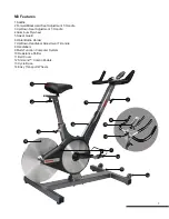
1
M3 Computer System Features
3
5
2
4
5
Содержание M3
Страница 1: ...M3 User and Service Manual...
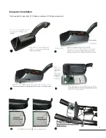
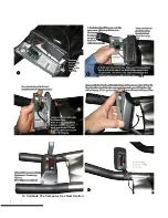
Страница 5: ...Computer Installation 3 Tools needed for assembly 1 Phillips screwdriver 2 Phillips screwdriver...
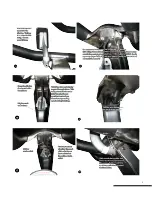
Страница 6: ...12 Calibrate The Computer See Next Section 4...
Страница 7: ...5...
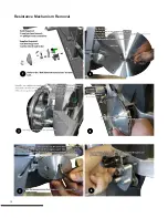
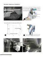
Страница 12: ...Resistance Mechanism Removal 10...
Страница 13: ...11...
Страница 14: ...Resistance Mechanism Installation 12...
Страница 15: ...13...
Страница 16: ...14...
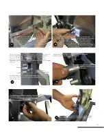
Страница 17: ...Steps For Belt Removal 15...
Страница 18: ...Steps for Belt Installation 16...
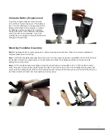
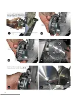
Страница 19: ...Crank Arm and Axle Removal and Installation 17...
Страница 20: ...18...
Страница 21: ...19...
Страница 25: ...23...
Страница 26: ...24...
Страница 27: ...25...


