background image

KBAC SERIES INSTALLATION AND OPERATION MANUAL 

22 

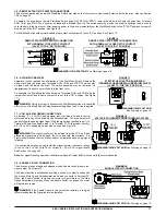
12.6 – SLIP COMPENSATION TRIMPOT (COMP) 

Sets the amount of Volts/Hz to maintain set motor speed under varying loads. The COMP 
Trimpot is factory set to 1.5 Volts/Hz, which provides excellent speed regulation for most 
motors. To increase the slip compensation, rotate the COMP Trimpot clockwise. To decrease 
the slip compensation, rotate the COMP Trimpot counterclockwise. See Figure 38. 
 

The slip compensation may be adjusted as follows: 
1.

  Wire an AC RMS ammeter in series with one motor phase. 

2.

 Run the motor and set the unloaded speed to approximately 50% (900 RPM on 4-pole 

1500/1725 RPM motors). 

3.

  Using a tachometer, record the unloaded speed. 

4

.  Load the motor to the nameplate rated current (AC Amps). 

5.

  Adjust the COMP Trimpot until the loaded RPM is equal to the unloaded RPM. 

6.

  The motor is now compensated to provide constant speed under varying loads. 


12.7 – MOTOR OVERLOAD (I

2

t) WITH RMS CURRENT LIMIT TRIMPOT (CL)* 

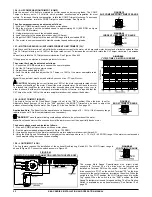
Sets the current limit (overload), which limits the maximum current to the motor, which prevents motor burnout and eliminates nuisance trips. 
The CL Trimpot is factory set to 160% of the drive rated current. To increase the current limit, rotate the CL Trimpot clockwise. To decrease 
the  
current limit, rotate the CL Trimpot counterclockwise. See Figures 39 and 40. 


*

UL approved as an electronic overload protector for motors. 


The current limit may be adjusted as follows: 
1.

  Connect an AC RMS ammeter in series with one motor phase. 

2.

  Set the CL Trimpot fully counterclockwise. 

3.

  Adjust the speed setting to 30%. 

4.

 Lock the motor shaft and adjust the CL Trimpot to 160% of the motor nameplate rated 

current. 


Note:

 This adjustment must be made within 6 seconds or an I

2

t Trip will occur. 


CAUTION!

 Adjusting the current limit above 160% of the motor nameplate rated current 

can cause overheating of the motor. Consult the motor manufacturer. Do not leave the motor 
in a locked rotor condition for more than a few seconds since motor damage may occur. In 
order to ensure that the motor is properly protected with the I

2

t feature, it is required that the 

CL Trimpot be set for 160% of the motor nameplate rated current, as described below. 


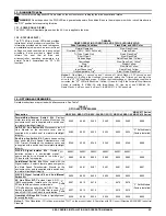
12.8 – BOOST TRIMPOT (BOOST) 

The drive is factory set for Fixed Boost (Jumper J6 set to the "FIX" position). When the drive is set for 
Adjustable Boost (Jumper J6 set to the "ADJ" position), the BOOST Trimpot can be used to adjust the 
amount of boost voltage to the motor. See Figure 41. Also see Section 10.5 on page 20. 
 

Application Note:

 The Boost function operates over a frequency range of 0 – 15 Hz. If the frequency range 

required is above 15 Hz, Boost adjustment is not necessary. 


WARNING!

 To avoid motor winding overheating and failure, do not overboost the motor. 


Note:

 An unloaded motor with excessive boost will draw more current than a partially loaded motor. 


The boost voltage may be adjusted as follows: 
1.

  Wire an AC RMS ammeter in series with one motor phase. 

2.

  Run the motor unloaded at approximately 4 Hz (or 120 RPM). 

3.

  Increase the boost until the ammeter reaches the motor nameplate rated current (Amps AC). 

4.

  Using the Main Speed Potentiometer, slowly adjust the motor speed over a 1 – 15 Hz (0 – 450 RPM) range. If the motor current exceeds 

the nameplate rating, decrease the boost setting. 


12.9 – JOG TRIMPOT (JOG) 

The Jog feature requires the installation of the optional Run-Stop-Jog Switch Kit. The JOG Trimpot range is 
shown in Figure 42. Connect the switch as sown in Figure 43. 


The orange Main Speed Potentiometer wire (wiper) which 
connects to Terminal P2 on the drive must be removed and 
installed on Terminal RUN on the switch. Terminal JOG on the 
drive connects to "JOG" on the switch. Terminal "P2" on the drive 
connects to the center (common) terminal on the switch. When the 
switch is in the "JOG" position, the JOG Trimpot is used to set the 
"jog" speed. When the switch is in the "RUN" position, the Main 
Speed Potentiometer is used for speed setting. The Run-Stop-Jog 
Switch is available as an optional accessory. See Section 14 on 
page 23. 

FIGURE 38 

SLIP COMPENSATION TRIMPOT RANGE

FIGURE 39 

CURRENT LIMIT TRIMPOT RANGE

FIGURE 40 

I

2

t TRIP TIME VS. MOTOR CURRENT

FIGURE 41 

BOOST TRIMPOT RANGE

FIGURE 42 

JOG TRIMPOT RANGE


FIGURE 43 

RUN-STOP-JOG SWITCH CONNECTION (SPDT WITH CENTER OFF)

*

Содержание KBAC-24D

Страница 1: ...G and 3G Models3 5 KBAC 24D 27D 29 29 1P 45 48 217 217S 217F 217SF 416 416S 416F 416SF The information contained in this manual is intended to be accurate However the manufacturer retains the right to...

Страница 2: ...anual Start Selection J3 19 10 4 Motor Frequency Selection J4 and J5 19 10 4 1 Setting the Drive for 50 Hz or 60 Hz Motor Operation J4 and J5 19 10 4 2 Setting the Drive for Two Times the Rated Motor...

Страница 3: ...ection J10 20 32 Switching Frequency and GFCI Selection Third Generation 3G Drives Only J12 20 33 Minimum Speed Trimpot MIN Range 21 34 Maximum Speed Trimpot MAX Range 21 35 Acceleration Trimpot ACCEL...

Страница 4: ...minals L1 L2 L3 AC Line input Rated for 208 230 Volt AC Line input only Rated for 2 HP maximum with 1 phase AC Line input and 3 HP maximum with 3 phase AC Line input KBAC 217 217S 217F 217SF Designed...

Страница 5: ...tilated 3 phase AC induction motors will overheat if used beyond a limited speed range at full torque Therefore it is necessary to reduce motor load as speed is decreased Note Some fan cooled motors c...

Страница 6: ...ided for easy installation of accessories Custom software all models can be factory programmed for applications which require special timing PLC functions and GFCI operation 4 1 STANDARD FEATURES Indu...

Страница 7: ...Specification Factory Setting 115 Volt AC Line Input Voltage Operating Range Volts AC 115 15 208 230 Volt AC Line Input Voltage Operating Range Volts AC 208 15 230 15 400 460 Volt AC Line Input Voltag...

Страница 8: ...selection See Section 10 4 on page 19 7 Jumper J12 Switching Frequency and GFCI selection Third Generation 3G drives only See Section 10 11 on page 20 8 Jumper J6 Adjustable Boost selection See Sectio...

Страница 9: ...er J4 Frequency Multiplier selection See Section 10 4 on page 19 8 Jumper J7 Regeneration or DC Injection Braking See Section 10 6 on page 20 9 Jumper J5 Motor Frequency selection See Section 10 4 on...

Страница 10: ...10 5 on page 20 7 Jumper J4 Frequency Multiplier selection See Section 10 4 on page 19 8 Jumper J7 Regeneration or DC Injection Braking See Section 10 6 on page 20 9 Jumper J5 Motor Frequency selecti...

Страница 11: ...IN Acceleration ACCEL Deceleration DECEL DC Injection Brake DECEL Boost BOOST Current Limit CL Jog JOG Slip Compensation COMP See Section 12 on pages 21 and 22 8 Selectable Jumpers Motor Horsepower J2...

Страница 12: ...are should be taken to avoid extreme hazardous locations where physical damage can occur When mounting the drive in an enclosure the enclosure should be large enough to allow for proper heat dissipati...

Страница 13: ...KBAC SERIES INSTALLATION AND OPERATION MANUAL 13 FIGURE 9 KBAC 27D 29 29 1P 45 48 MECHANICAL SPECIFICATIONS Inches mm Tighten these screws in the sequence shown to 12 in lbs 14 kg cm...

Страница 14: ...KBAC SERIES INSTALLATION AND OPERATION MANUAL 14 FIGURE 10 KBAC 217 217S 217F 217SF 416 416S 416F 416SF MECHANICAL SPECIFICATIONS Inches mm...

Страница 15: ...e cover making sure that the wires do not get caught or crimped as the cover is closed Tighten the four screws so that the gasket is slightly compressed The recommended tightening torque is 12 in lbs...

Страница 16: ...Ground Wire Earth to the Green Ground Screw The Ground Screws are located next to Terminal Block TB1 See Figures 11 13 on pages 15 and 16 7 4 REMOTE MAIN SPEED POTENTIOMETER CONNECTION The drive is su...

Страница 17: ...iometer setting when the AC Line is applied 7 7 VOLTAGE FOLLOWING CONNECTIONS An isolated 0 5 Volt DC analog signal input can also be used to control motor speed in lieu of the Main Speed Potentiomete...

Страница 18: ...tic ramping then the hi pot output must be manually increased to the test voltage and then manually reduced to zero This procedure must be followed for each machine to be tested A suggested hi pot tes...

Страница 19: ...econds the drive will shut down and then ride through and automatically return to the set frequency See Figure 24 If Jumper J3 is set to the M position the drive will have to be manually restarted for...

Страница 20: ...Y Jumper J12 is factory set to the 8K position for a switching frequency at the motor of 8 kHz For 12 kHz switching frequency set Jumper J12 to the 12K position This jumper also allows the drive to be...

Страница 21: ...ot exercised The Safety Warnings on page 5 must be read and understood before proceeding 12 1 MINIMUM SPEED TRIMPOT MIN Sets the minimum speed of the motor The MIN Trimpot is factory set to 0 of frequ...

Страница 22: ...or is properly protected with the I2 t feature it is required that the CL Trimpot be set for 160 of the motor nameplate rated current as described below 12 8 BOOST TRIMPOT BOOST The drive is factory s...

Страница 23: ...urce and the drive Mounts on the drive s PC board with four snap ins 2G 9600C 9600C 9600C 9600C 9600C 9600C 3G1 8890 8890 8890 8890 8890 8890 8890 Auto Manual Switch Kit When used with the Signal Isol...

Страница 24: ...on and removal inconvenience or consequential damage including injury to any person caused by items of our manufacture or sale Some states do not allow certain exclusions or limitations found in this...

Отзывы: