background image

Instructions for use ERGOcom 3
5 Operation

 | 

5.1 Operation, general

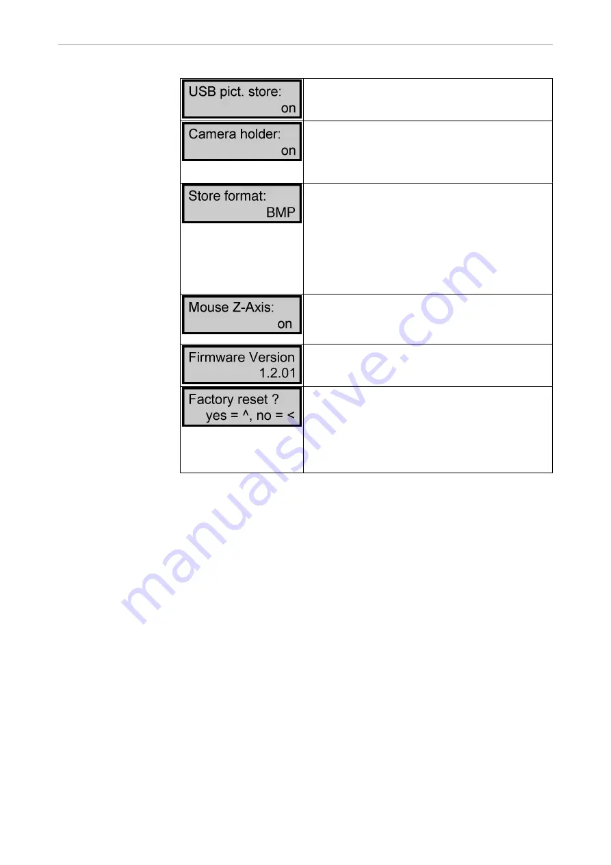
On: When saving in Video mode, the images are saved

to USB drive ERGOCOM3.

Off: Nothing is saved to USB drive ERGOCOM3.
On: Once the internal/external camera is removed from

its holder, the photographic image automatically dis‐

plays on screen.

Off: Automatic operations are not available. The came‐

ra image has to be selected manually.

Determining the image format in which the images are

to be saved to the USB drive.

BMP stands for bitmap and is supported by all com‐

monly used image processing programs. The current

YUV format is converted to BMP beforehand (taking 6

seconds or less to save).

YUV stands for video format and is supported by only

a few programs. However, this format can be saved

much faster (in under 2 seconds).

This is for use with ERGOremote, for determining how

the Z axis of the joystick is to be used.

On: You can use joystick to click or double-click.

Off: You cannot use joystick to click or double-click.

Displays Firmware version number for ERGOcom 3

mainboard.

Reset all menu items to factory settings.

CAUTION: Selecting this command also resets VGA

IN, VGA OUT, VIDEO IN and VIDEO OUT to their fac‐

tory settings.

Yes: Choose the up arrow to activate the factory reset.

No: Choose the left arrow to leave the settings as they

are.

See also: 5.3.15 Footswitch mode, Page 40

24/54

Содержание ERGOcom 3

Страница 1: ...Instructions for use ERGOcom 3 Always be on the safe side...

Страница 2: ...Sales KaVo Dental GmbH Bismarckring 39 D 88400 Biberach 49 7351 56 0 Fax 49 7351 56 1488 Manufacturer Kaltenbach Voigt GmbH Bismarckring 39 D 88400 Biberach...

Страница 3: ...2 1 General 9 2 2 2 Product specific 9 2 3 Safety instructions 10 2 3 1 General 10 2 3 2 Product specific 10 3 Product description 11 3 1 Product name 11 3 2 Controls 12 3 3 Connections 13 3 4 Rating...

Страница 4: ...IDEO OUT 1 image source 34 5 3 6 Setting VIDEO OUT 2 image source 35 5 3 7 Audio signals 36 5 3 8 Generate still 36 5 3 9 Save still 37 5 3 10 Change display view 38 5 3 11 Select image 38 5 3 12 Dele...

Страница 5: ...chnician s instructions SFC Safety checks IEC International Electrotechnical Commission RI Repair instructions EMC Electromagnetic compatibility 1 1 2 Symbols See safety hazard warning symbol chapter...

Страница 6: ...GOcom 3 1 User Notes 1 2 Service 1 2 Service Service hotline 49 7531 56 2700 Service Multimedia kavo com Please indicate the product serial number in all requests Additional information can be obtaine...

Страница 7: ...no com pelling legal provisions opposing it KaVo shall not be liable for defects and their consequences which occur as a result of normal wear and tear or of improper cleaning and maintenance non obse...

Страница 8: ...ecipient must record the loss or damage on the notice of receipt The reci pient and transport company employee delivering the product must both sign the notice of receipt 2 Leave the product and packa...

Страница 9: ...without there being any noticeable damage to the packa ging upon delivery you must proceed as follows 1 Report the damage to the transport company as soon as possible within 7 days of delivery 2 Leave...

Страница 10: ...vers necessary measures for avoiding hazards 2 1 3 Description of hazardous steps Safety instructions with three hazard levels are used in this document for avoiding personal and property damage CAUTI...

Страница 11: ...is in a satisfactory condition before each use During use national legal regulations must be observed in particular the applicable health and safety regulations the applicable accident prevention reg...

Страница 12: ...d systems such as pacemakers Consult the patient before treatment The KaVo product is not permitted to be used in areas subject an explosion hazard The following individuals are authorised to repair a...

Страница 13: ...omfort and excellence These models differ from one another in terms of their in built components Model Components classic No display interface No radio master ERGOremote comfort With display interface...

Страница 14: ...LED blue Navigation right Standby Navigation down VGA IN 1 VGA IN 2 button Delete image images VIDEO IN 1 VIDEO IN 2 CAMERA button Freeze Status display VIDEO OUT 2 button Configuration OSD menu VIDE...

Страница 15: ...1 Mains connection AUDIO IN 2 Mains fuse VIDEO IN 2 MONITOR POWER AUDIO OUT 1 MONITOR VGA monitor 1 VIDEO OUT 1 CAMERA AUDIO OUT 2 USB DOWN downstream VIDEO OUT 2 USB UP upstream AUDIO VGA IN 1 21 CON...

Страница 16: ...plate 3 4 Rating plate SN Serial number REF Material number Type ERGOcom 3 device type HF emission Note consult accompanying documents VDE label CE label Consult user instructions CSA label FCC label...

Страница 17: ...Hz Power consumption 70 VA Ambient conditions for operation Permissible operating temperature 0 40 C Permitted relative air humidity 5 95 Ambient conditions for transport and storage Permitted transpo...

Страница 18: ...temperature due to poor ventilation can lead to malfunc tion or failure Do not set up near to a heat source Do not cover the product s vents A minimum gap of 50 mm must be left in front of and behind...

Страница 19: ...nel 1 for treatment room 1 Hold down the Channel Selection Learn Channel Mode button for 2 seconds The channel selected appears on the status display Note If no entry is made within 8 seconds the ERGO...

Страница 20: ...do not synchronise within approximately 30 seconds ERGOcom 3 returns to operating mode Hold down the Wake Up Learn button on the ERGOremote for more than 3 se conds The green LED will flash to indica...

Страница 21: ...sing the enclosed CD the USB patch is installed automatically Microsoft SP2 contains this patch If the KaVo Device Interface System is not installed the USB patch can be installed later from CD D CCCD...

Страница 22: ...om 3 is switched off this memory is deleted This memory is used to store stills and can store up to a maximum of 8 stills at a time The images contain the following name syntax Bildxx_y bmp xx image n...

Страница 23: ...onvert the image into an image size of 720 x 576 dpi with a colour depth of 24 bit Save this image as a bitmap naming it USERLOGO bmp Drag the USERLOGO bmp file over to the ERGOCOM3 USB drive Note The...

Страница 24: ...lights up blue The status display and display are switched off and all device settings are retai ned Press Standby again to return to operating mode Note Standby mode helps to extend the service life...

Страница 25: ...esolution and image fre quency SXGA 50 Hz or SXGA 60 Hz is 19 1280 x 1024 dpi XGA 50 Hz or XGA 60 Hz is 15 1024 x 768 dpi To ensure optimum image display quality you must use the same screen size 15 o...

Страница 26: ...t YUV format is converted to BMP beforehand taking 6 seconds or less to save YUV stands for video format and is supported by only a few programs However this format can be saved much faster in under 2...

Страница 27: ...ource must be active 5 2 1 Operating mode In operating mode you can switch between the VGA or VIDEO image sources in cluding audio signal that are shown on KaVo screen 1 Note Video images can only be...

Страница 28: ...equirement Your PC needs a grabber card to show VIDEO image sources on screen 1 VIDEO OUT 1 must then be connected up to the grabber card Press the VIDEO IN button If a VGA image source was selected b...

Страница 29: ...VGA OUT image source Hold down the VGA OUT button for 2 seconds The last image source selected is shown in the status display The status display returns to operational mode after 5 seconds See also 5...

Страница 30: ...n the status display 5 2 5 Setting VIDEO OUT 1 image source The VIDEO OUT 1 button on ERGOcom 3 classic is inactive If you select the VIDEO OUT 1 button not available will appear as a message on the s...

Страница 31: ...The status display flashes and setting mode is activated Select the required VIDEO input port by pressing the VIDEO IN button Note If no entry is made within 8 seconds the ERGOcom 3 returns to operati...

Страница 32: ...The KaVo Device Interface System software is installed on the PC Hold down the footswitch for 2 seconds The Generate still command is transmitted to the PC 5 2 9 Save still Requirement The ERGOcom 3...

Страница 33: ...s please note the following To view the selected option on screen 1 the relevant source must be active 5 3 1 Operating mode In operating mode you can switch between the VGA or VIDEO image sources in c...

Страница 34: ...VIDEO IN 1 or VIDEO IN 2 the logo that was set in the OSD Display Interface menu will be displayed See also 5 4 5 Menu point other Page 44 5 3 3 Setting VIDEO IN image source Press the VIDEO IN butto...

Страница 35: ...VIDEO IN 1 or VIDEO IN 2 the logo that was set in the OSD Display Interface menu will be displayed See also 5 4 5 Menu point other Page 44 5 3 4 Setting the VGA OUT image source Hold down the VGA OUT...

Страница 36: ...VGA OUT to select the required VGA input Note If no entry is made within 8 seconds the ERGOcom 3 returns to operating mode This saves the last setting on the status display 5 3 5 Setting VIDEO OUT 1 i...

Страница 37: ...display flashes and setting mode is activated Select the required VIDEO input port by pressing the VIDEO IN button 5 3 6 Setting VIDEO OUT 2 image source Hold down the VIDEO OUT 2 button for 2 second...

Страница 38: ...IDEO input port by pressing the VIDEO IN button Note If no entry is made within 8 seconds the ERGOcom 3 returns to operating mode This saves the last setting on the status display 5 3 7 Audio signals...

Страница 39: ...PC by USB cable The grabber card is connected to VIDEO OUT 1 or VIDEO OUT 2 The KaVo Device Interface System software is installed on the PC Hold down the Freeze button for 2 seconds The save is show...

Страница 40: ...ge number of the active image is shown in white Press the full screen quad mode button again to return to full screen mode 5 3 11 Select image Select the required image using the 4 navigation buttons...

Страница 41: ...ted and the logo selected in the OSD menu display interface is shown or Requirement 4 stills are generated using the multifunction foot control See also 5 3 8 Generate still Page 36 Press the footswit...

Страница 42: ...itch controls are as follows Situation Live image Still Camera removed Press footswitch The current video signal generates a still Press footswitch 2 seconds The still is saved in the ERGO COM3 USB dr...

Страница 43: ...ra holder off The logo is displayed When the footswitch is pressed the ERGOcom 3 goes to the next still 1 4 or logo Press footswitch 2 seconds The ERGOcom 3 toggles between full screen and quad mode 2...

Страница 44: ...ll OSD menu display interface Requirement The image source whose screen settings are to be changed must be selected See also 5 2 1 Operating mode Page 25 5 3 15 Footswitch mode Page 40 Hold down the O...

Страница 45: ...se by 1 or toggle bet ween yes or no Save changed setting 5 4 3 VGA main menu There is a separate main menu for every VGA IN image source This allows the settings on Display 1 to be defined and saved...

Страница 46: ...ed and saved for every image source Note The requisite explanations of the individual menu items or settings are shown di rectly on screen 1 5 4 5 Menu point other This menu point is available in all...

Страница 47: ...Instructions for use ERGOcom 3 5 Operation 5 4 Operation OSD menu display interface 45 54...

Страница 48: ...damage to surfaces is very much dependent on the reaction times of these sub stances it is essential for any spilled substances to be wiped away immediately using a damp cloth Detergent recommended K...

Страница 49: ...sinfection CAUTION Damage caused by fluids Faults in electrical components Protect product openings from the penetration of fluids Remove fluids from unit interior Wipe surface with a soft fluff free...

Страница 50: ...Instructions for use ERGOcom 3 6 Preparation methods DIN EN ISO 17664 6 3 Maintenance 6 3 Maintenance The product does not require regular user maintenance 48 54...

Страница 51: ...Safety checks 7 Safety checks If an EC3 Display is integrated with an ERGOcom 3 safety checks SFC must be performed every 2 years A detailed description of SFC can be found in the engineer s instructi...

Страница 52: ...DVD has been inserted Check image source No camera image is displayed Treatment unit switched off Switch on treatment unit Poor video quality Poor image material Only use image material that is of goo...

Страница 53: ...ERGOcom 3 are listed in the PC device manager as follows Note Some entries in the device manager are governed by the connected PC Device manager list of ERGOcom 3 classic Virtual com port touchscreen...

Страница 54: ...st Device manager list of ERGOcom 3 comfort Virtual com port touchscreen HIDcomlnst exe Touchscreen driver Cam control HID interface USB 2 0 PC host controller ERGOcom control HID interface 7 port hub...

Страница 55: ...e Virtual com port touchscreen HIDcomlnst exe Touchscreen driver Cam control HID interface USB 2 0 PC host controller ERGOcom control HID interface 7 port hub in ERGOcom 3 HID interfaces for wlink mas...

Страница 56: ...terface Full screen mode A full screen image is displayed Quad mode Four separate images are shown on screen OSD menu ERGOcom 3 comfort excellence The on screen menu of the display interface This is...

Страница 57: ......

Страница 58: ...1 003 1610 KF 2005 09 03 en...

Отзывы: