


11
10
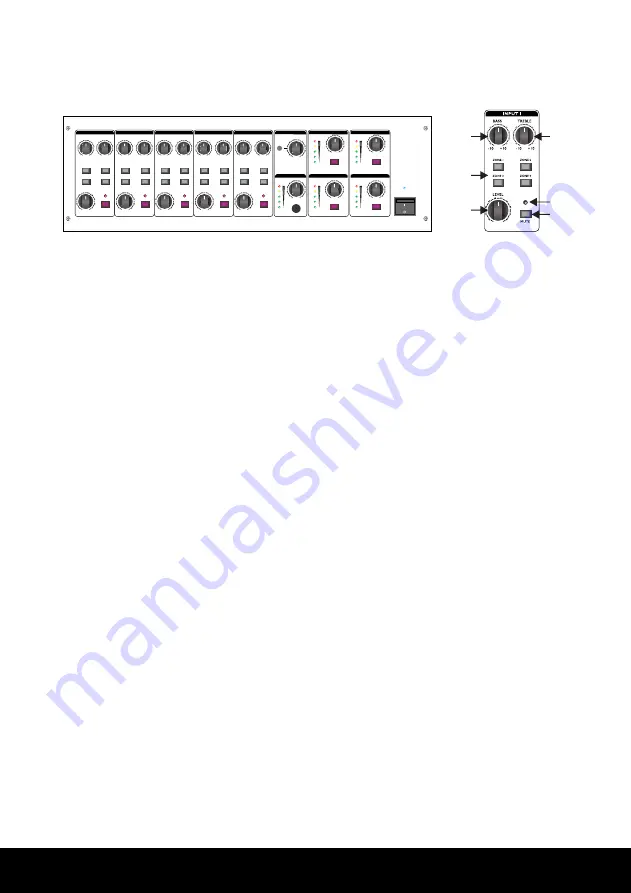
Pannello frontale
Front panel
1.
CONTROLLO BASSI
Il controllo bassi consente di accentuare e
amplificare i suoni più gravi, come la voce
maschile, la grancassa della batteria e la
chitarra basso. Il range di guadagno va da
-10dB a +10bB e la frequenza centrale è di
100Hz.
2.
SELETTORE ZONA
I tasti Z1, Z2, Z3, Z4 consentono
l’assegnazione delle zone. Premete il tasto
Z1 e il segnale verrà assegnato alla zona
1. Ripremete di nuovo il tasto per disattivare
quella zona. I tasti Z2, Z3, Z4 funzionano
analogamente.
3.
CONTROLLO VOLUME
Sul valore 0 dB il volume è al minimo. Sul
valore 10 dB il volume è al massimo.
4.
MANOPOLA TREBLE
E’ il controllo degli alti. Può essere utilizzato
per eliminare i rumori legati alle alte frequenze
o per accentuare i suoni più acuti della voce
umana o di strumenti come i piatti. Il range
di guadagno va da -10dB a +10bB e la
frequenza centrale è di 10 kHz.
1.
BASS KNOB
This is the bass control. Boost male voice or
kickdrum and bass guitar. Your system will
sound much bigger than what it is. The gain
range goes from -10dB to +10dB and the center
frequency is 100 Hz.
2.
ZONE SELECTOR
The keys Z1,Z2,Z3,Z4 can be considered as
signal assignment switches. Press the button Z1
down and the signal will be assigned to ZONE 1.
Release the button to disable ZONE1. The keys
Z2, Z3,Z4 operate in the same way.
3.
VOLUME CONTROL
When it is 0 dB, the volume is lowest, it is 10 dB,
the volume is highest.
4.
TREBLE KNOB
This is the treble control. You can use it to get rid
of high frequency noises or to boostthe sound
of cymbals or the high harmonics of the human
voice. The gain range goes from -10dB to 10dB
with the central frequency 10kHz.
INPUT 1
LEVEL
ZONE
LINE 15V MIC
GAIN
TEL
Line out(nal/unbal)
Power Amp output
4
8
25V
70V
100V
COM
G
ZONE 1
Line out(nal/unbal)
Power Amp output
4
8
25V
70V
100V
COM
G
ZONE 2
Line out(nal/unbal)
Power Amp output
4
8
25V
70V
100V
COM
G
ZONE 3
Line out(nal/unbal)
Power Amp output
4
8
25V
70V
100V
COM
G
ZONE 4
MONITOR
TEL.PAGING
MONITOR
PRIORITY
Line out
1W
INPUT 2
INPUT 3
INPUT 4
INPUT 5
GAIN
GAIN
GAIN
GAIN
LINE 15V MIC
LINE 15V MIC
110-120V~50/60Hz:T6.3A 250V
220-240V~50/60Hz:T3.15A 250V
~AC IN
AC SELECT
230V
115V
5
REAR PANEL
16. AC CONNECTOR AND AC FUSE
This connector is meant for the connection of the spplied mains cord, The
fuse protects the alternating currents supply circuit of the equipment. The
fuse can only be changed in the event of a fault.
12. MONITOR selector
Push MONITOR button down, then it connects the signal from amplifier 1 to monitor volume.
Release the button, then it cuts off the signal connection to monitor volume. The other three
buttons are operated in the same way.
This switch is used to select voltage (115V / 230V) as requirement.
15. VOLTAGE SWITCH
PL
POWER
ON
OFF
13
14
13. PL
This LED is the power indicator. When the amplifier is powered on, this LED
lights up. When the amplifier is powered off, this LED lights off.
14. POWER SWITCH
When the switch is set in the position ON, the unit is powered on. When the switch is set in
the position OFF, the unit is powered off.
AC SELECT
115V
230V
15
110-120V~50/60Hz:T6.3A 250V
220-240V~50/60Hz:T3.15A 250V
~AC IN
16
These terminals allow connecting speakers.
18. POWER AMP OUTPUT
70V
4
Line out(bal/unbal)
Power Amp output
8
50V
COM
100V
Connecting the speakers to 4 ohm output
+
4 ohm
ZONE 3
ZONE 2
ZONE 1
70
V
COM
100
V
4
Line out(bal/unbal)
+
8
50
V
Power Amp output
70
V
COM
100
V
4
Line out(bal/unbal)
+
8
50
V
Power Amp output
70
V
COM
100
V
4
Line out(bal/unbal)
+
8
50
V
Power Amp output
ZONE 4
70
V
4
Line out(bal/unbal)
+
Power Amp output
8
50
V
COM
100
V
17
18
17. LINE OUT BAL/UNBAL
These terminals can be connected with other appliance, such as amplifier, recorder, etc.
4
FRONT PANEL
1. BASS KNOB
This is the Bass control. Boost male voice or kickdrum and bass guitar. Your system will
sound much bigger than what it is. The gain range goes from -10dB to
+10dB and the center frequency is 100 Hz.
1
2
3
4
5
6
2. ZONE SELECTOR
Z1, Z2,Z3,Z4 can be considered as signal assignment switches. Press
the button Z1 down and signal will be assigned to ZONE 1. Release the
button and it stopsAssigning signal to ZONE1. Z2, Z3,Z4 can be oper-
ated in the same way.
3. VOLUME CONTROL
When it is 0 dB, the volume is lowest, it is 10 dB, the volume is highest.
4. TREBLE KNOB
This is the treble control. You can use it to get rid of high frequency noises or to boost
the sound of cymbals or the high harmonics of the human voice. The gain range goes
from -10dB to 10dB with the central frequency 10kHz.
5. MUTE LED
When the mute key is pressed down, mute LED lights up, and vice versa.
6. MUTE
It mutes the signals from the corresponding channel.
7. HEADPHONE VOLUME CONTROLLER
This knob controls the volume of Phone (refer to 7).Turn the knob clockwise,
and it increases the volume, and vice versa.
8. PHONE
This jack is for headphone output.
PHONE
LEVEL
0 10
7
8
9. MONITOR VOLUME
This knob controls the output signal level to monitor output.
MONITOR
LEVEL
0 10
9
10. ZONE VOLUME
VOLUME controls the output signal level of ZONE.
10
12
11
11. LED VU-METER
This stereo 5 segment LED-meter indicates the level of the overall
output signal.
0 10
0 10
0 10
0 10
0 10
0 10
0 10
0 10
0 10
0 10
0 10
0 10
0 10
INPUT 1
INPUT 2
INPUT 3
INPUT 4
INPUT 5
AUX
ZONE 1
ZONE 2
ZONE 1
ZONE 2
MONITOR
BASS
TREBLE
TREBLE
BASS
TREBLE
BASS
BASS
TREBLE
TREBLE
BASS
LEVEL
-10
+10
-10
+10
-10
+10
-10
+10
-10
+10
-10
+10
-10
+10
-10
+10
-10
+10
-10
+10
ZONE 1
ZONE 2
ZONE 1
ZONE 2
ZONE 2
ZONE 1
ZONE 2
ZONE 1
ZONE 2
ZONE 1
ZONE 3
ZONE 4
ZONE 3
ZONE 4
ZONE 4
ZONE 3
ZONE 4
ZONE 3
ZONE 4
ZONE 3
LEVEL
LEVEL
LEVEL
LEVEL
LEVEL
MUTE
MUTE
MUTE
MUTE
MUTE
LEVEL
LEVEL
LEVEL
MON
MON
MON
MON
LEVEL
LEVEL
POWER
INPUT 1
LEVEL
ZONE
LINE 15V MIC
GAIN
TEL
Line out(nal/unbal)
Power Amp output
4
8
25V
70V
100V
COM
G
ZONE 1
Line out(nal/unbal)
Power Amp output
4
8
25V
70V
100V
COM
G
ZONE 2
Line out(nal/unbal)
Power Amp output
4
8
25V
70V
100V
COM
G
ZONE 3
Line out(nal/unbal)
Power Amp output
4
8
25V
70V
100V
COM
G
ZONE 4
MONITOR
TEL.PAGING
MONITOR
PRIORITY
Line out
1W
INPUT 2
INPUT 3
INPUT 4
INPUT 5
GAIN
GAIN
GAIN
GAIN
LINE 15V MIC
LINE 15V MIC
110-120V~50/60Hz:T6.3A 250V
220-240V~50/60Hz:T3.15A 250V
~AC IN
AC SELECT
230V
115V
5
REAR PANEL
16. AC CONNECTOR AND AC FUSE
This connector is meant for the connection of the spplied mains cord, The
fuse protects the alternating currents supply circuit of the equipment. The
fuse can only be changed in the event of a fault.
12. MONITOR selector
Push MONITOR button down, then it connects the signal from amplifier 1 to monitor volume.
Release the button, then it cuts off the signal connection to monitor volume. The other three
buttons are operated in the same way.
This switch is used to select voltage (115V / 230V) as requirement.
15. VOLTAGE SWITCH
PL
POWER
ON
OFF
13
14
13. PL
This LED is the power indicator. When the amplifier is powered on, this LED
lights up. When the amplifier is powered off, this LED lights off.
14. POWER SWITCH
When the switch is set in the position ON, the unit is powered on. When the switch is set in
the position OFF, the unit is powered off.
AC SELECT
115V
230V
15
110-120V~50/60Hz:T6.3A 250V
220-240V~50/60Hz:T3.15A 250V
~AC IN
16
These terminals allow connecting speakers.
18. POWER AMP OUTPUT
70V
4
Line out(bal/unbal)
Power Amp output
8
50V
COM
100V
Connecting the speakers to 4 ohm output
+
4 ohm
ZONE 3
ZONE 2
ZONE 1
70
V
COM
100
V
4
Line out(bal/unbal)
+
8
50
V
Power Amp output
70
V
COM
100
V
4
Line out(bal/unbal)
+
8
50
V
Power Amp output
70
V
COM
100
V
4
Line out(bal/unbal)
+
8
50
V
Power Amp output
ZONE 4
70
V
4
Line out(bal/unbal)
+
Power Amp output
8
50
V
COM
100
V
17
18
17. LINE OUT BAL/UNBAL
These terminals can be connected with other appliance, such as amplifier, recorder, etc.
4
FRONT PANEL
1. BASS KNOB
This is the Bass control. Boost male voice or kickdrum and bass guitar. Your system will
sound much bigger than what it is. The gain range goes from -10dB to
+10dB and the center frequency is 100 Hz.
1
2
3
4
5
6
2. ZONE SELECTOR
Z1, Z2,Z3,Z4 can be considered as signal assignment switches. Press
the button Z1 down and signal will be assigned to ZONE 1. Release the
button and it stopsAssigning signal to ZONE1. Z2, Z3,Z4 can be oper-
ated in the same way.
3. VOLUME CONTROL
When it is 0 dB, the volume is lowest, it is 10 dB, the volume is highest.
4. TREBLE KNOB
This is the treble control. You can use it to get rid of high frequency noises or to boost
the sound of cymbals or the high harmonics of the human voice. The gain range goes
from -10dB to 10dB with the central frequency 10kHz.
5. MUTE LED
When the mute key is pressed down, mute LED lights up, and vice versa.
6. MUTE
It mutes the signals from the corresponding channel.
7. HEADPHONE VOLUME CONTROLLER
This knob controls the volume of Phone (refer to 7).Turn the knob clockwise,
and it increases the volume, and vice versa.
8. PHONE
This jack is for headphone output.
PHONE
LEVEL
0 10
7
8
9. MONITOR VOLUME
This knob controls the output signal level to monitor output.
MONITOR
LEVEL
0 10
9
10. ZONE VOLUME
VOLUME controls the output signal level of ZONE.
10
12
11
11. LED VU-METER
This stereo 5 segment LED-meter indicates the level of the overall
output signal.
0 10
0 10
0 10
0 10
0 10
0 10
0 10
0 10
0 10
0 10
0 10
0 10
0 10
INPUT 1
INPUT 2
INPUT 3
INPUT 4
INPUT 5
AUX
ZONE 1
ZONE 2
ZONE 1
ZONE 2
MONITOR
BASS
TREBLE
TREBLE
BASS
TREBLE
BASS
BASS
TREBLE
TREBLE
BASS
LEVEL
-10
+10
-10
+10
-10
+10
-10
+10
-10
+10
-10
+10
-10
+10
-10
+10
-10
+10
-10
+10
ZONE 1
ZONE 2
ZONE 1
ZONE 2
ZONE 2
ZONE 1
ZONE 2
ZONE 1
ZONE 2
ZONE 1
ZONE 3
ZONE 4
ZONE 3
ZONE 4
ZONE 4
ZONE 3
ZONE 4
ZONE 3
ZONE 4
ZONE 3
LEVEL
LEVEL
LEVEL
LEVEL
LEVEL
MUTE
MUTE
MUTE
MUTE
MUTE
LEVEL
LEVEL
LEVEL
MON
MON
MON
MON
LEVEL
LEVEL
POWER