


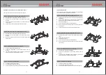


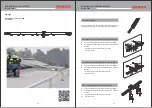


Step 3A: Assembling the Cable Extremity: Ref. PN 7000 (03)
Ÿ
of the cable extremity.
Ÿ
Open the strands of the wire.
Ÿ
Insert the core of the cable in the poke pin. The core is the straight
strand, all other strands are twisted.
Ÿ
With a hollow Center-punch hammer the poke pin deep inside the
housing of the cable extremity
Ÿ
Tighten the connector of the extremity to the housing of the cable
extremity.
Ÿ
Connect the cable extremity to the mounting bracket (for the upper
ladder rung) by a locking pin.
Ÿ
Insert the pin ring in to the locking pin to lock.
Open up the cable roll and then insert the cable in to the housing
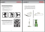
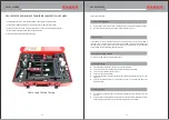
Wire Crimping
Assembly PN7000(14)
(Step 3B)
Aluminum
Ferrules
Aluminum
Endcap
SS Thimble
Heat Shrink
Tube
CABLE TERMINATION
Ref. PN 7000
STEP 3B: Wire Crimping Assembly PN 7000 (14):
Ÿ
Insert 2 ferrules in the wire.
Ÿ
Insert the wire in heat shrinking tube.
Ÿ
Loop the wire across the Stainless Steel Thimble.
Ÿ
Insert the end of the wire back into the Ferrule.
Ÿ
Crimp the Ferrule using a 20 Ton Hydraulic Crimping head and
2
300mm crimping dies.
Ÿ
Ensure that the first ferrule is as close as possible to the thimble, the
next ferrule should be 50mm apart from the first one.
Ÿ
Insert the aluminum cap in the free end of wire and crimp it.
Ÿ
Cover the entire assembly up to the bottom edge of the ferrule with a
heat Shrinkable tube.
Ÿ
Shrink the tube with a hot air gun.
Cable\ Extrimit
Poke\ Pi
STEP 1
STEP 2
STEP 3
STEP 4
05
04
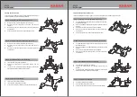
STEP 3C: Cable Swaging
Ÿ
Insert the cable into the swage tube
Ÿ
The swage tube has markings to identify exact positions of crimping
Ÿ
Place the swage tube on the hex loc die of a hydraulic crimping
tool(130kN capacity).
Ÿ
Ensure that the mark on the swage tube is in the center of the die.
Ÿ
Operate the machine to start the swaging operation until the green
light is on.
Ÿ
Repeat the process for all markings(5 times minimum).
STEP 3D: U bolt & Thimble
Ÿ
Loop the Cable across the thimble and ensure at least 300mm of the
cable is overlapping.
Ÿ
Next, fasten the stainless steel U bolts (Part of Ref PN 6000 (01))
approximately 50 mm apart.
Ÿ
If the cable is in excess make a loop and tie the loop with cable ties.
Ÿ
If it is necessary to cut the cable, seal the loose end of the cable by
adhesive tape after cutting it.
50mm
Ubolt & Thimbles
PN 6000 (01)
(Step 3D)
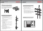
SHOCK ABSORBER &
Ref. PN 7000
CABLE TERMINATION
Ÿ
Connect the shock absorber to top mounting bracket by inserting
the fastener and the nylon spacer so as to pass through mounting
bracket and eye of energy absorber.
Ÿ
The spacer ensure the correct position of energy absorber.
Ÿ
Ensure that the energy absorber is fitted with red arrow on label
pointing down wards
Ÿ
Connect the end extremity to energy absorber by inserting
fastener through eye of energy absorber.
Step 02 -
Installation of Shock Absorber
A suitable cable termination may be selected according to the site
condition u-bolts and thimbles are only Allowed at bottom termination
according to EN353.1:2014
Step 03- Cable Termination