14
PAGE
Repair Instructions
K 350
Assembling the
spindle
(mounting the
outer parts)
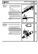
1
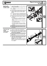
Mount the cup springs (47) (see illustra-
tion).
2
Mount the clutch (the stop washer (48)
with indentations against the toothing of
the spindle gear (49)).
3
Fit the spring ring (50) and press it
on (against the pressure of the cup
springs (47)).
4
Mount the slides (43) and the retaining
plate (45).
5
Mounting the rear thrust bearing assem-
bly:
– profile ring with damper O-ring (51)
– two compensating washers (65)
– thrust bearing (52)
– washer (58)
6
Secure the rear thrust bearing assembly
with the locking washer (53).
Mounting
the spindle
1
Fasten the spindle (46) to the motor hous-
ing (27) with the two screws (85) (6 Nm,
for additional security use Loctite 222 or
Omnifit.).
2
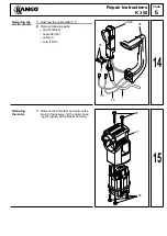
Push the ring gear (38) over the back gear
shaft (29) and let it engage in the locking
slide (43).
3
Push the planetary gear (37) onto the
back gear shaft (29) and fit them into the
ring gear (38).
4
Push the straight pin (44) through the lock-
ing slide (43) and insert it into the motor
housing (27).
Mounting the
gear housing
1
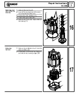
Insert a service tool (A) into the gear (25)
(the sleeve protects the corrugated seal
ring inside the gear (25) from damage dur-
ing assembly).
2
Fit the gasket (87) to the gear
housing (25).
3
Fasten the gear box (25) to the motor
housing (27) and fix it with bolts (85)
(2,5+0,5Nm).
4
Fit the switch lever (87) (mount it in the
“hammer” position, the pin must grasp the
elongated hole of the locking slide).
53
45
43
50
49
48
47
51
65
58
52
12
43
85
46
27
44
37
38
29
13
A
25
87
27
87
85
14
Содержание K 350
Страница 1: ......


