background image

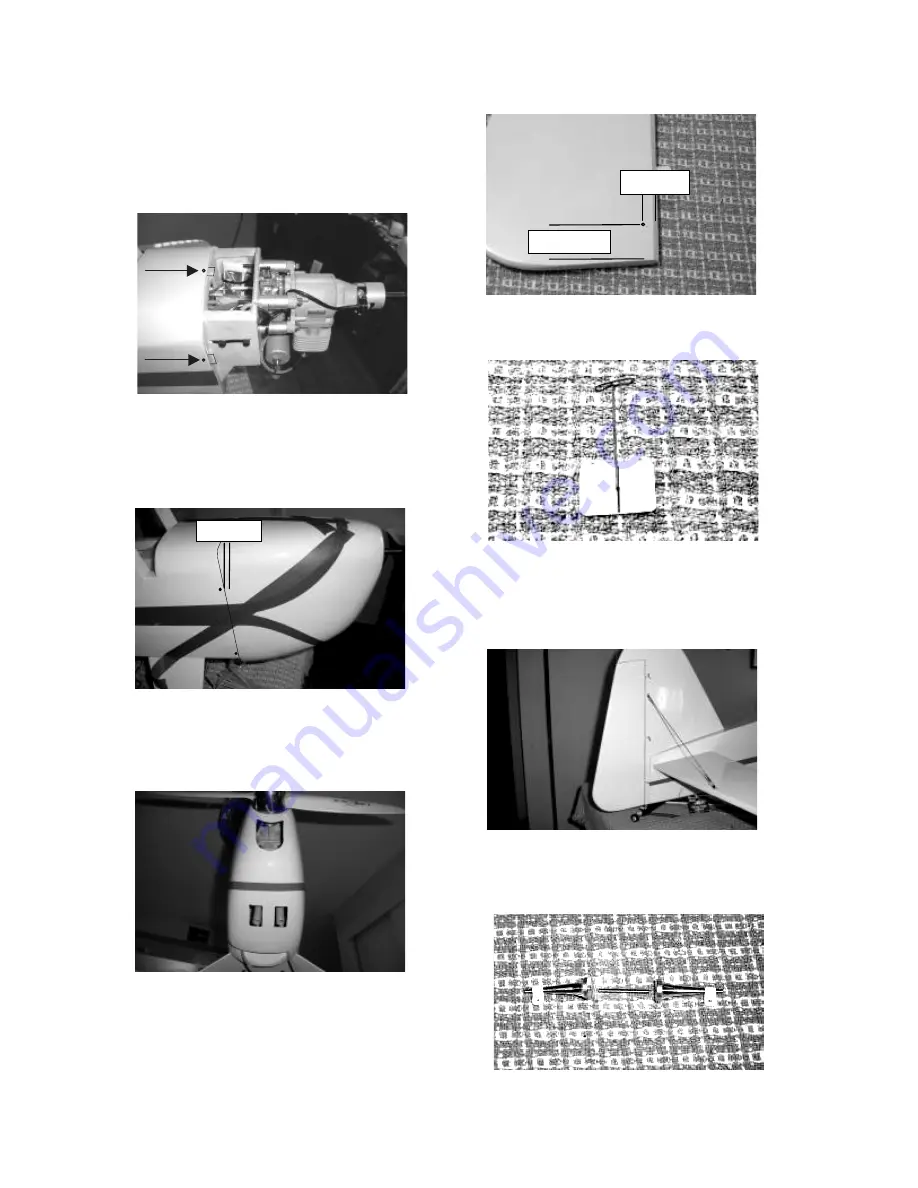
Complete the engine installation 
following the manufacture 
instructions. Use a felt tip pen to make 
a dot at the center of each cowl mount 
tab. 

1/2-inch

1 1/8-inch

 
Securely tap the cowl in place; make 
sure it is butted against the fuselage. 
Drill 1/16-inch holes in the cowl 1/4-
inch forward of the back edge. 

 
Locate and open the necessary holes 
for your engine. Be sure to open a hole 
in the front large enough to insure 
good cooling. 

 
Drill a 1/8-inch hole in the rudder for 
the control horns. Locate the hole  
1 1/8-inch up from the bottom and 
1/2-inch back from the hinge line. 

 
Locate the center of each hinge, and 
insert a pin through the hinge. 

1/4-inch

 
Install the hinges in the rudder, then 
the rudder on the fin. Align carefully, 
remove the pins and apply two drops 
of thin CA to each side of each hinge. 

 
Use the two long control horns with 
the threaded rod for the rudder pull-
pull. 


Содержание Rearwin Speedster

Страница 1: ...s In no case shall Kangke Industrial s liability exceed the purchase cost of this kit Since Kangke Industrial has no control of final assembly and material used by user for final assembly no liability shall be assumed or accepted for any damage resulting from the use of user assembled products This kit has been flight tested for normal use If the plane will be used for extremely high stress flying...

Страница 2: ...n to be appreciated Capable of all basic and most advanced aerobatics even the average pilot looks like a pro Blazing high speed passes followed by slow gentle landings attract attention from all that see it fly The engine of choice for the proto type was the ZDZ 40 distributed by RC Showcase The narrow width excellent power light weight and reliability made for a perfect combination RC Showcase 3...

Страница 3: ...ines this manual should be considered a guide in those areas Always follow the manufacture instructions for those components Read each step of the instructions carefully Be sure you understand what is required and what the procedure is before you glue or cut anything How well you assemble this model will have a direct effect on its flight characteristics If you are familiar with the assembly of AR...

Страница 4: ...nstall the block with the supplied wood screws and washers Save the springs and rudder bracket for installation later Locate the hardware bag for the main gear and install it as shown with four screws and washers this bag also contains the wing attach screws and the upper hatch lower pan screws Locate the holes for the flying wires in the stabilizer and fin The holes are small and difficult to fin...

Страница 5: ...quare if necessary Clean the excess epoxy with a paper towel moistened with alcohol Open the three holes in the covering for the fin as shown Coat the mating surface of the fin with a thin layer of epoxy It is not necessary to remove any of the covering Install the fin starting with the lower pin tapping gently forward Remove the excess epoxy with a paper towel moistened with alcohol Open the hard...

Страница 6: ...ical center will be 2 inches up from the bottom of the engine box The distance from the firewall to the propeller flange or spinner must be between 6 7 8 inches and 7 1 4 inches 6 7 8 to 7 1 4 inches 2 inches Assemble the fuel tank with the proper stopper for your fuel type The proto type uses a three line system with two vents out the bottom this will only work with gas Check your engine manufact...

Страница 7: ...les for your engine Be sure to open a hole in the front large enough to insure good cooling Drill a 1 8 inch hole in the rudder for the control horns Locate the hole 1 1 8 inch up from the bottom and 1 2 inch back from the hinge line Locate the center of each hinge and insert a pin through the hinge 1 4 inch Install the hinges in the rudder then the rudder on the fin Align carefully remove the pin...

Страница 8: ...rough the slots at the rear of the fuselage Some modelers like to cross the cables others do not The choice is yours Fabricate the rudder end of the cable in the same way Adjust the cables so that with the servo and rudder on center there is no free play Do not over tighten the cables Exit slot Drill a 1 8 inch hole in each elevator half for the control horn Locate the hole 1 inch out and 3 8 inch...

Страница 9: ...ds Install the wing strut attach bracket at the back edge of the main gear Cut a small relief in the belly pan to clear the strut bracket Relief Install the belly pan with the supplied screws Assemble the wheels and axles Slide the axle through the wheel followed by the spacer and the standard nut Install the anti rotation screw followed by the axle and tighten Supplied wood screws Anti rotation 9...

Страница 10: ...sing the provided string the pull the wire through Drill a 1 8 inch hole in the aileron 1 2 inch behind the hinge line Install the short control horns With the servo centered install and adjust the push rod Align the aileron carefully Locate and open the holes for the wing strut attach brackets as shown and install the brackets 1 2 inch 2 inches 7 3 4 inches Install the wing tube in the fuselage s...

Страница 11: ...lane off the ground It should hang from 10 degrees nose down to 10 degrees nose up CONTROL THROWS With your radio on center all trims and adjust the clevises so all control surfaces are straight Measure the control surface movement at the widest part of each surface Use the servo horns and bell crank holes to adjust the control throw For your first flights the control throws should be set to the f...

Страница 12: ...traight It may be necessary to correct the aileron trim after this procedure Continue to fly and trim until the aircraft is tracking well land before the fuel runs out Carry a little power on final approach until over the end of the runway then cut power to idle hold the plane just off the runway till the airspeed bleeds off and the plane settles on If the landing is too long add power go around a...

Отзывы: