background image

!

PGND

!

!

!

!

!

!

!

GND

GND

PGND

PGND

GND

GND

GND

GND

GND

GND

GND

GND

PGND

PGND

GND

PGND

GND

GND

PGND

GND

GND

T

!

VAL?

VAL?

GND

T

T

T

T

T

GND

PGND

T

GND

PGND

PGND

PGND

VDD

FSW

COMP

GND1

ISET

PWMI

EN

FB4

FB3

FB2

FB1

OVP

GND2

CS

GATE

VCC

V

N3

N1

N4

N2

E1,E2

GATE

CS

VDD

RT

FB

GND

T

!

!

!

T

T

T

T

T

T

T

!

!

!

T

T

T

T

T

!

!

!

T

V 1.0

2.5V/2K=1.25mA

LED Driver

MS08FP

MS08FP.SCH

+50VLED

NC

R838

ZPC1

R833

1K

FR207

D801

D802

FR104

2

4

3

1

L81

F81

3.15A

250VAC

ZL

ZN

ZPGND

1

2

CN800

12V

Z50V

ZPCGND

R83

1M2

R81

1M2

R84

1M2

R82

1M2

NTC81

1R5

ZVCC1

ZHV

GND

12V

12V-1

GND-1

1

2

3

4

PC820

TLP781

ZPC2

ZFB

1R5

NTC82

0.47U

CX81

2

3

1

D850A

MBR10150

6

4

5

3

2

1

U801

RT7736

4

3

2

1

L82

VCC1

2

4

1

3

5

12

11

10

9

8

7

6

T801

D850

MUR460

R850

33R

2

3

1

D830

MBR10150

VR81

680V

13

8

15

3

6

16

9

5

4

2

1

7

14

10

11

12

U770

GB98A

FSW

VCC

R779A

100K

R779B

NC

LED3

LED4

C776

330P

C775

1U

C773

1U

R795

0R

C82

68U

450V

L770

120UH

ZLED4

C805

10U
50V

C805A

10U
50V

R813

10R

R812 10R

VS

R834

2K

12V

ZLED3

12V

ZLED2

ZLED1

ZLED+

Z12V

1

2

3

4

CN802

FSW

C774

100P

B801

100P

C807

1000P

C830

B770

R832

10K

NC

Q770

A0D256

R785

0.33R

EN

25V

470U

C832

C851

47U

100V

R824

0R

FB

C806

100P

R853B

4.7K

ZD851

33V

R853A

4.7K

ZD850

33V

12VOUT

R823

0R

R822

0R

C808

2200P

R821F

150K

220P

C850

R852

33R

R851

33R

ZGND

C783

22U

160V

C852

47U

100V

C833

470U

25V

1

2

3

4

5

6

7

8

9

10

CN701

R819A

0.56

R819B

0.56

VLED+

R798 0R

CY81

1000P

CY82

1000P

BR

C853B

0.1U

C853A

0.1U

C771

0.1U

C772

100P

R775 470K

R776

1K

R777

200R

ISET

R778

6K8

R773

10K

DIM_PWM

R772

100K

R771

10K

BL_ON

R770 100R

12V

R780 22R

R782

10K

OVP

R790A

12K

R790B

NC

R821E

150K

R821C

150K

R821D

150K

R821B

150K

R821A

150K

C81

68U

450V

R806

510K

R804

510K

R805

510K

BR

R807B

8.2K

8.2K

R807A

R797

0R

B

E

C

Q802

BT3906

R818

10R

R814
470R

R801

300K

R802

300K

R803

300K

D83

RL255

D81

RL255

C782

330P

C781

330P

C780

330P

C779

330P

C778

1000P

C777

330P

1U

C770

R796

0R

R794

220K

R793

220K

R792

220K

R791

220K

R789

1M

R786

0.33R

R784

0.33R

R783

0.33R

ZD770 10V

D770

SB5200

R839

39K

R837

6K8

R836

22K

R835

10K

C836

0.1U

C835

0.1U

3

2

1

U830

TL431

C834

0.1U

C831

470U

25V

R831

33R

R830

33R

1

2

3

4

HS1

R815

22R

R816

10K

R817 22R

C802

10N

C801

0.1U

C803

1000P

Q801

AOTF11C60

ZD801

22V

D84

RL255

CY83

NC

D82

RL255

VCC1

+50VLED

LED4

LED3

LED2

LED1

FB

12V

OVP

LED1

LED2

LED3

LED4

PWMI

ISET

10R

R788

R781

1K

R774

100K

PWMI

VLED+

HV

12VOUT

HV

VS

VLED+

LED2

LED1

VCC

0.22U

CX82

VCC1

+50VLED

Содержание K-LED43FHDRST2

Страница 1: ...cation 3 Alignment Procedure 4 Block diagram 5 Scheme Diagram 6 Troubleshooting SORGH GUDZLQJ This manual is the latest at the time of printing and does not include the modification which may be made after the printing by the constant improvement of product ...

Страница 2: ...stitute a risk of electric shock to the person The exclamation point within an equilateral triangle is intended to alert the user to the presence of important operating and maintenance servicing instructions in the literature accompanying the appliance CAUTION Use of controls adjustments or procedures other than those specified herein may result in hazardous radiation exposure CA U T ION RISK RISK...

Страница 3: ... television set to impact of any kind Be particularly careful not to damage the picture tube surface 9 Unplug this television set from the wall outlet before cleaning Do not use liquid cleaners or aerosol cleaners Use a damp cloth for cleaning 10 1 Do not place this television set on an unstable cart stand or table The television set may fall causing serious injury to a child or an adult and serio...

Страница 4: ...nit size of grounding conductors location of antenna discharge unit connection to grounding electrode and requirements for the grounding electrode 15 2 Note to CATV system installer Only for the television set with CATV reception This reminder is provided to call the CATV system attention to Article 820 40 of the NEC that provides guidelines for proper grounding and in particular specifies that th...

Страница 5: ...Feature Definition Specification Company Confidential File Drafted by Date 2015 7 7 Checked by 43 D1400 3MS08GP LA FDS Approved by ...

Страница 6: ...78 5 86 3 578 5 Dimension w Package 1128 137 665 Net Weight With Stand Kg 7 4 Net Weight Without Stand Kg 7 2 Gross Weight With Packaging Kg 9 7 20 feet pcs 264 40 feet pcs 540 40 feet high pcs 716 53 feet high w Pattet pcs 630 Language of User Manual Remote Control Model RC199E Batteries 2 AAA Stand Packed with TV set Picture Sound Terminals Refer to MB Worksheet 5 Band EQ 110 240 75 Note 1 H60 1...

Страница 7: ...in Display Port CI Slot 1 CI 1 3 Mains 8 type S P DIF Coaxial Audio out Yes SD Slot No MHL No Energy Saving No Rohs No Energy Effficiency CB Yes HDMI No MHL No Dolby No DTS No SRS No SRRC No Wifi No Bluetooth No Miracast No DLNA No CTS No Output max 2 8W Languages Input Voltage VAC 110 240 Rated Power W 75 Standby Power W 0 5 1 IEC169 2 1 No No 1 mini 1 Terminals PSU Only for 3 in 1 Spanish Englis...

Страница 8: ...Type1 TV Descriptions Yes or No Remarks Analogue PAL Yes NTSC Yes SECAM No Digital DVB T2 Yes Multimedia Formats Video H 264 MPEG1 MPEG2 DIVX Motion JPEG VC1 Yes Audio MP3 AC3 HE AAC LPCM WMA Yes Pictures JPEG BMP PNG MPO Yes Special Functions User Manual English Yes ...

Страница 9: ...1 13 Alignment Procedure MS08GP Series VERSION V1 0 PREPARED BY Gongjunzan DATE 2015 3 23 APPROVED BY DATE ...

Страница 10: ... Mode press RIGHT or LEFT key Select User Mode Press the subsequence RCU keys 9 7 3 and 5 will appear in the left top of screen In case of Factory hotKey is enabled On just press RCU Return key to pop up again the Factory menu The status of Factory Key can be changed in Factory Menu Hotkey Press RCU OK key or RIGHT key to enter the submenu Press RCU Menu key to go back to the root menu Press RCU R...

Страница 11: ...NOTE Not adjust OK 4 White balance White Balance data adjustment refer as follow The balance data is set by PE before the mass production Do not need adjust OK 5 SHOP init Option DO Reset the set after production alignment This operation will remove all unnecessary factory value The factory hotkey will be turn off OK 6 NVM reset DO System initialization Restore all data except the White Balance an...

Страница 12: ...ss OK 10 Deviceld test This item only factory used Note Below the factory menu some model information are showed including software version Project Name SIACP Version and SW release time 3 ADC Submenu NOTE ADC Date use Default Setting do without adjust 4 WHITE BALANCE Submenu ITEMS Default Setting Description Statu s Source Current Source Current Source HDMI1 need adjustment Other Source not use O...

Страница 13: ...RY MENU ON OFF OK 2 SHOP Setting Default setting submenu after production alignment refer to OK 3 Other Setting Other set Only for TCL R D OK 4 SERVICE menu After service menu description OK 5 PARAM SETTING Parameter setting submenu OK 6 HOTEL MENU Hotel submenu not adjust OK SHOP INIT submenu ITEMS Default Setting Description Status Volume 30 0 100 adjustable OK PIC MODE STANDARD Normal Vivid Mil...

Страница 14: ...ev Off Off 1 2 3 not adjust OK SSCOM Debug on On Off not adjust OK DTV Off On Off not adjust OK Reset Shop Do Wait not adjust OK BGM On On Off not adjust OK WSS ATF On On Off not adjust PARAM SETTING Picture Curve ITEMS Default Setting Description Status Brightness Curve Brightness curve Exclusively used by R D OK Contrast Curve Contrast curve Exclusively used by R D OK Color Curve Color curve Exc...

Страница 15: ...vely used by R D OK SSC adjust SSC SSC adjust Exclusively used by R D Overscan Adjust Over Scan Over Scan Exclusively used by R D DBC DBC DBC Exclusively used by R D Back Light Curce Back Curve Back curve Exclusively used by R D OK Audio amp Setting Audio amp Setting Audio amp Setting Exclusively used by R D OK DTV Para Setting DTV Para Setting DTV Para Setting Exclusively used by R D OK ...

Страница 16: ...ontrol Left and right the cursor keys will Factory hotkey set to ON 2 WARM UP is set to ON according to the panel on the menu button to exit the aging mode OK 3 ADC ADC calibration refer as follow NOTE Not adjust OK 4 White balance White Balance data adjustment refer as follow The balance data is set by PE before the mass production Do not need adjust OK 5 SHOP init Option DO Reset the set after p...

Страница 17: ...de MAC Address 10 Deviceld test This item only factory used ok 5 Debugging 5 1 General Steps of debugging According to the requirement of the order below steps are needed for appropriate setting 1 Enter the Factory Menu enable FAC HOTKEY 2 Check Project ID and the version of software release date displayed at the bottom of Factory Menu 3 Enter Design Menu choose SERVICE MENU Project ID choose corr...

Страница 18: ...he ADC status only PC and YPbPr is success and Color Analyzer has been calibrated Only AV1 YPbPr PC HDMI1 need to be adjusted HDMI1 should be the first 5 4 1 Signal and generator The pattern of the signal should be used are White Chroma2329 pattern 113 and Grey pattern 114 The format of signal are respectively 720P for HDMI1 Chroma2329 Timing 69 PAL Chroma2329 Timing38 for AV1 1024X768 60Hz Chroma...

Страница 19: ... by tools Position Chip type Software description U301 MT29F2G08ABAEA HDMI HDCP Key System Software etc 7 Software update Method of SW update 1 Download the bin file to the root directory of your USB device Do not change the file name Then insert the USB device to USB interface of TV set MS08GPSeries with its upgrade file corresponding relation as thetable below show Chassis Name Sales area Upgrad...

Страница 20: ...Plug USB stick to the TV Press and hold the power key of key board before reconnect AC cord to restart TV for 5 8seconds Once USB stick starts blinking TV is uploading SW BIN image When update is successful TV should restart automatically Remember to perform Factory menu NVM reset and then press RCU OK key Switch off TV by removing AC cord Reconnect AC cord to restart TV and wait few seconds for E...

Страница 21: ...PP IC TSOP48 13 FS29F2 G0B Mboot Main Software 2 The MAC Address HDCP KEY Device ID must be upgrade by debug port into U301 8 Project ID selecting 1 Press the Menu button of remote control then select Contrast item of Picture submenu press 1 9 5 0 consecutively there you go the Design Menu 2 Select the SERVICE MENU item press OK and RIGHT button of the remote to enter submenu 3 Select the PROJECT ...

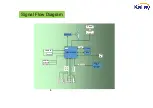
Страница 22: ...DS Transimiter TPA3113D SPI MSD6308RT HDMI2 HDMI3 FAT FAT FLASH Key IR VEDIO IN Audio out Audio in Network DDR SPDIF Signal Flow Diagram Panel USB 1 HDMI1 CABLE ATV ANATENA ATV DTV RX RX D D WIFI D D DDR ...

Страница 23: ...Power Supply Block Diagram 2 ...

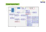
Страница 24: ...3 Power Supply Flow Power transform 52v ...

Страница 25: ...8PA MSD6308RT TU101 Tuner TU101 Tuner I C Bus Block Diagram TU1_SCL TU1_SDA 4 HDMI1 HDMI1 HDMI1_SCL HDMI1_SDA HDMI2 HDMI2 HDMI2_SCL HDMI2_SDA HDMI3 HDMI3 HDMI3_SCL HDMI3_SDA ...

Страница 26: ...17 0R R016 150K If Vout 1 18V Set R015 150K R017 120k R016 33K C035 22U 6 3V C019 22U Q010 2N7002K R029 4K7 NC R028 4K7 NC R045 0R C039 10U R027 1K NC R026 39K NC R016 33K 1 40 MS08GP MAA2HG 12 5 2014_10 07 7 GJZ C010 220U 10V 470R R009 C044 22U 6 3V 100K R007 NC 5V 5V R038 330R 12K R037 3_3V C027 0 1U C028 10U Z3_3VSVB 3_3V B C E Q002 BT3904 0 1U C024 POWER_ON 82K R008 POWER_ON R046 1K R036 33R R...

Страница 27: ...5R R918 75R C905 0 1U C907 0 1U R919 75R F901 F900 RXVN_1 RXVP_1 TXVN_0 TXVP_0 1 2 3 4 5 6 7 8 9 10 11 12 13 14 15 16 U900 TS8121CLF 75R R917 NET_TXC NET_TX1P NET_TX1N NET_RX1P NET_RX1N NET_RXC 3 4 5 6 7 8 1 2 9 10 11 12 P902 RX1N TXC RX1P TX1N TX1P RXC NET_RXC NET_RX1N NET_TXC NET_RX1P NET_TX1N NET_TX1P C916A 1000P R257 33R F919 F918 F917 F916 F915 F914 F913 F912 C274 0 047U ZVGA B R259 33R R991 ...

Страница 28: ... 1U R929 0R R942 10K R941 4K7 C914 0 1U H_CEC H_CEC H_CEC H3_SDA H3_HPD H3_5V H3_SCL H3_HPD H3_HPD_OUT B C E BT3904 Q403 R936 4K7 R934 10K R935 1K R933 100R R932 100R R931 47K R930 47K H3_5V H3_SDA H3_SCL H3_RXC H3_RXC H3_RX0 H3_RX1 H3_RX1 H3_RX2 15 16 2 5 8 11 17 19 13 14 7 9 4 6 1 3 10 12 18 P904 AVDD5V_MHL R945 33R H2_HPD_OUT H2_HPD C926 2U2 H1_ARC R927 1K R925 100R R924 100R R921 100R R923 47K...

Страница 29: ...70R NC C214 0 1U C215 0 1U R210 10K C241 30P C240 30P FAT _D 10 6 7 8 1 3 2 4 5 9 TU1 T_SDA T_SCL TU1_VCC TU1_VCC IF C102 22P TUNER_FAT B E C BT3906 Q200 B E C BT3906 Q201 L201 600R B C E Q900 BT3904 1 2 3 D200 BAT54C MCU_RESET C503 2U2 C260 10U 3_3VSB 1_5V 1_5V C233 0 1U NC C231 0 1U 3_3V 3_3VSB R232 0R C245 1U AVDD_DMPLL AVDD_AU C222 0 1U C226 0 1U NC C227 0 1U C221 0 1U C223 0 1U C224 0 1U C302...

Страница 30: ...ND76 VDDC7 MCP_VDDC MCP_VDDC1 GND77 GND78 GND79 GND80 GND81 GND82 GND83 GND84 VDDC DGND T PCMCIA PIN PCMCIA PIN H LEVEL PM_CONFIG1 close to SOC PM_CONFIG0 LG_DIM_OUT SPI_SDI Chip config Chip config PIN H L H PCMCIA PIN PCMCIA PIN PCMCIA PIN TO NANDFLASH CLOSE TO MAIN IC C253 4U7 PCM_A7 PCM_A6 RF_SW LG_DIM_OUT PM_CONFIG1 SPI_SDI PM_CONFIG0 ZCVBS_OUT C290 0 1U N12 N13 N14 N15 P12 P13 P14 M12 A7 M14 ...

Страница 31: ... 22R 5 4 7 2 1 3 6 8 R347 22R 5 4 7 2 1 3 6 8 R348 22R 5 4 7 2 1 3 6 8 R349 22R B DDR3 DQU5 B DDR3 BA2 B_DDR3_CS0 B_DDR3_DQSUB B_DDR3_DQSLB B_DDR3_DQSUB B_DDR3_DQSU B_DDR3_DQSLB B_DDR3_DQSL B_DDR3_MCLKZ B_DDR3_MCLK B_DDR3_CKE B_DDR3_RESET B_DDR3_BA2 B_DDR3_BA2 B_DDR3_BA1 B_DDR3_BA0 B_DDR3_ODT B_DDR3_DMU B_DDR3_DML B_DDR3_WEZ B_DDR3_RASZ B_DDR3_CASZ B_DDR3_DQU6 B_DDR3_DQU4 B_DDR3_DQU0 B_DDR3_DQU7 B...

Страница 32: ...3 24 22 9 10 11 12 28 U600 TPA3113D2 C616 330P R617 10R C613 330P C600 220U 16V HP_R HP_L C622 0 1U 50V C614 0 1U 50V 1U 50V C636 HP_R HP_L C617 0 1U 50V 12VA AMP_R OUTLP OUTLN OUTRN OUTRP L600 392170 C629 1U C628 1U 12VA 12V 0R R634 R631 10K GAIN1 GAIN0 R622 10R 1U C602 1U C608 1U C607 C612 0 22U R628 10R R611 100R L602 220R NC R613 10K C626 0 1U C611 0 1U C625 1000P C610 1000P L606 22UH L603 22U...

Страница 33: ... C832 C851 47U 100V R824 0R FB C806 100P R853B 4 7K ZD851 33V R853A 4 7K ZD850 33V 12VOUT R823 0R R822 0R C808 2200P R821F 150K 220P C850 R852 33R R851 33R ZGND C783 22U 160V C852 47U 100V C833 470U 25V 1 2 3 4 5 6 7 8 9 10 CN701 R819A 0 56 R819B 0 56 VLED R798 0R CY81 1000P CY82 1000P BR C853B 0 1U C853A 0 1U C771 0 1U C772 100P R775 470K R776 1K R777 200R ISET R778 6K8 R773 10K DIM_PWM R772 100K...

Страница 34: ...D PERSONS COPIEDUNLESS PERMITTED IN WRITING FORMAT DIN A4 NOTE PAGE OF IR VCC GND T ZLS IR_OUT LED_IN 1K5 R4 BT3906 Q2 C E B IR 3V3 LED 470R R6 BT3904 Q1 E C B 100R R2 470R R3 D1 3 1 2 1K5 R5 4K7 R7 0BAV99 D2 2 3 1 100R R1 LS 1U C3 100K R4 AT442 G2 E 2 C P1 1 2 3 4 5 6 7 AT138B IR1 5V LOGO GND LS C1 10U 3V3 GND 3V3 ...

Страница 35: ... no picture Check the voltage of pin s of q208 2 1 Replace R270 and R271 Check the output of Q208 2 1 Check the voltage of g of Q208 OR replace Q208 Measure the wave of LVDS signal 1 2 Replace panel Check the supply of U201 ...

Страница 36: ...he wave of pin 8 9 of U1 1 Check the voltage of pin 6 7 of u1 OK Replace u1 Check the circuit between U1 and U201 Check the U201 measure the wave of SDA and SCL 1 repair the circuit of U101 and Q102 OK OK 1 Check the U201 OK ...

Страница 37: ... Check the components between VGA YPbPr port and U201 1 Replace the bad VGA YPbPr no picture OK Check the components between VGA YPbPr port and U201 1 Replace the bad Software of U202 ok 1 Check U201 ok OK OK 1 Replace the bad Replace U201 1 Replace the bad Check the peripheral components of U201 ...

Страница 38: ...pin 3 13 of U602 2 1 Repair the 12v supply Check the pin 6 of u602 2 1 Check q607 q608 q609 1 2 Replace U602 or replace the wire of speaker check u601 and volume control Check the wave of PIN 4 12 of U602 Check the pin 7 of u602 2 1 repair R691 and R692 ...

Страница 39: ...andby 5 0VSB OK 5 0V NG Check the voltage of pin s of q305 2 1 Check before Q305 Check the output of Q305 2 1 Check the voltage of g of Q305 OR replace Q305 Check U303 U304 short to Gnd 1 Replace the bad ...

Страница 40: ...The picture bad Replace the wire from P202A to t com Replace panel Replace the chassis NG Check the circuit between p202a and U201 Upgrade the software NG OK OK ...

Страница 41: ......

Отзывы: