KVAULT ODD Replacement
December 2020
101-0269-00 Rev 2
Page 14 of 24
New A-Frame Bracket Procedure
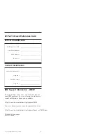
Mark the Locations of the Bracket
The vault is calibrated at the factory to allow for chassis tolerances. Keeping
the brackets aligned to the current positions will help ensure proper
operation.
1.
With a fine-tip felt marker, mark the perimeter of the square hole to
the left of the rollers.
2.
Also mark the perimeter of the oblong hole at the top right. This will
aid in ensuring the assembly is properly aligned when reassembling.
Figure 20
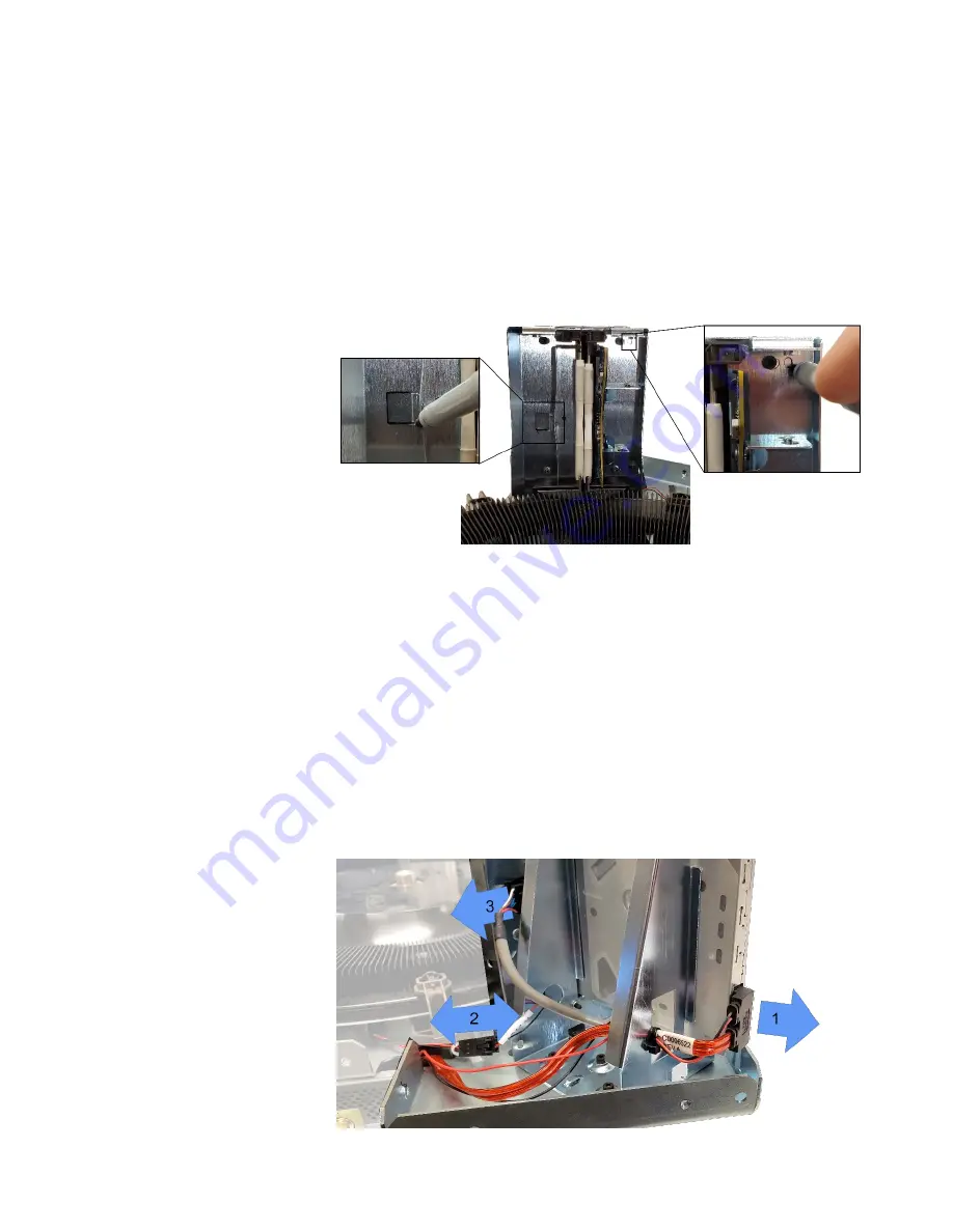
Remove Old Optical Disc Drive
Cut the zip-tie on bottom of the drive bracket to free the cables. Be careful
not to nick the cables.
1.
Remove the red SATA cable from the back of the disc drive by
pinching both sides and pulling straight back. Push cable end through
the rectangular bracket hole. See Figure 21.
2.
Disconnect the two-pin motor cable by depressing the latch
separating the two connectors. Push the cable end through the round
bracket hole. See Figure 21
3.
Disconnect the sensor board cable by depressing the latch and
pulling the connector straight out. See Figure 21.
Figure 21