05
-21
39
-16
48
-11
58
33
57
In heating mode, the maximum leaving water flow temperature
(T1stoph) that heat pump can reach in different outdoor
temperature (T4) is listed below:
In DHW mode, the maximum domestic hot water tempera-
ture(T5stop) that heat pump can reach in different outdoor
temperature(T4) is listed below:
The unit have a freeze prevention function that uses the heat
pump to keep the water system safe from freezing in all
conditions. Since a power failure may happen when the unit is
unattended, It's suggested to use anti-freezing flow switch in
the water system. (Refer to 9.4 Water piping).
In cooling mode, the minimum leaving water flow tempera-
ture(T1stoph) that the unit can reach in different outdoor
temperature(T4) is listed below:
COOLING MODE
Outdoor temp. (°C)
Water flow temp. (°C)
Outdoor temp. (°C)
Water flow temp. (°C)
Outdoor temp. (°C)
Water flow temp. (°C)
≤10
10
14
8
18
6
11
9
15
7
19
6
12
9
16
7
20
5
13
8
17
6
≥21
5
-25
35
-20
40
-15
50
34
56
-10~30
60
-24
35
-19
42
-14
52
35
55
-23
35
-18
44
-13
54
31
59
-22
37
-17
46
-12
56
32
58
Outdoor temp. (°C)
Water flow temp. (°C)
Outdoor temp. (°C)
Water flow temp. (°C)
Outdoor temp. (°C)
Water flow temp. (°C)
Outdoor temp. (°C)
Water flow temp. (°C)
Outdoor temp. (°C)
Water flow temp. (°C)
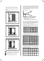
①
Heat pump capacity.
②
Required heating capacity (site dependent).
③
Additional heating capacity provided by backup heater.
Tbivalent
Outdoor temperature
Capacity/Load
③
②
①
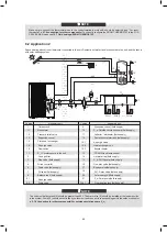
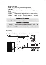
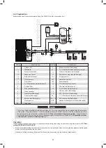
Solar kit for domestic hot water tank(field supply)
An optional solar kit can be connected to the unit.
Remote alarm kit (field supply) can be connected to
the unit.
Operation range
HEATING MODE
If you add the backup heater in the system, the backup heater
can increase the heating capacity during cold outdoor
temperatures. The backup heater also serves as a backup in
case of malfunctioning and for freeze protection of the outside
water piping during winter time. The capacity of backup heater
for different units is listed below.
Outdoor temp. (°C) -25~-21 -20~-14 -15~-11 -10~-4
DHW Water flow
temp. (°C)
DHW Water flow
temp. (°C)
DHW Water flow
temp. (°C)
35
40
45
48
55
55
53
53
50
48
Outdoor temp. (°C)
0~4
5~9
10~14
-5~-1
Outdoor temp. (°C)
15~19
25~29 30~34
20~24
50
50
35~39 40~43
48
45
Outdoor temperature(°C)
Water flow temperature (°C)
Outdoor temperature(°C)
Water flow temperature (°C)
DOMESTIC WATER HEATING MODE
Outdoor temperature(°C)
Water flow temperature (°C)
No heat pump operation, IBH or AHS only
Water flow temperature drop or rise interval
If IBH/AHS setting is valid, only IBH/AHS turns on;
If IBH/AHS setting is invalid, only heat pump turns on;
*If the system is installed in parallel,Tbt1 must be connected and installed in the balance tank.
**If the volume of the balance tank is relatively large, in order to ensure the use effect, it is recommended to add a Tbt2 sensor
in the lower part of the balance tank.
**When the units are connected in parallel, such as when the communication between the unit is unstable (such as an
Hd
fault code),
add a network matching wire between the ports H1 and H2 at the terminal of the communication system;
Sensors Tbt1, Tbt2, T5 and extension wire can be shared, sensors Tw2, Tsolar and extension wire can be shared, if these functions
are needed at the same time, please customize these sesors ande extension additionally.
3 ACCESSORIES
06
To avoid injury, do not touch the air inlet or aluminum fins of the unit.
Do not use the grips in the fan grills to avoid damage.
The unit is top heavy! Prevent the unit from falling due to improper inclination during handling.
CAUTION
Before installation:
Be sure to confirm the model name and the serial number of the unit.
Handling:
Due to relatively large dimensions and heavy weight, the unit should only be handled using lifting tools with
slings. The slings can be fitted into foreseen sleeves at the base frame that are made specifically for this purpose.
4 BEFORE INSTALLATION
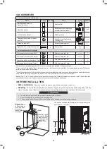
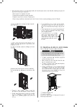
The position of barycenter for different unit can be seen in the
picture below. (unit:mm)
304
670
425
670
Installation and owner’s
manual(this book)
Quantity
Operation manual
Technical data manual
Shape
Name
Name
Accessories supplied with the unit
Adapter for inlet water pipe
+sealing ring
Thermistor for domestic hot water
tank (T5) *
1
1
1
Quantity
Shape
1+1
Tighten belt for customer wiring use
2
1
1
1
Extension wire for T5
1
Y-shape filter
1
Water outlet connection pipe
arubber stopper
Wired controller
2+2
1
Network matching wire***
1
Extension wire for Tbt1
Thermistor for balance tank (Tbt1)*
1
1
Extension wire for Tbt2
Thermistor for balance tank (Tbt2)**
1
1
Extension wire for Tw2
Thermistor for Zone 2 flow temp. (Tw2)
1
1
Extension wire for Tsolar
Thermistor for solar temp. (Tsolar)
Accessories avaliable from supplier
The hook and
barycenter of the
unit should be on
a line in vertical
direction to
prevent improper
inclination
Make the rope go
through the lifting
holes from both
the right and left
sides in the
wooden collet
≥
1000mm
Energy label
1
89
88
Содержание MONO KHC-22RX3
Страница 1: ...INSTRUKCJA INSTALACYJNA INSTALATIONMANUAL POMPA CIEPŁA MONO MONO TYPE HEAT PUMP PL EN ...
Страница 2: ......
Страница 79: ...79 ...
Страница 80: ......
Страница 157: ...NOTE 157 ...
Страница 158: ...NOTE ...
Страница 159: ...16125300002403 V C ...
Страница 160: ...kaisai com ...


