


29
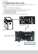
8.1 NETWORKER INSTALLATION KUN4 & KUN5
8.1.1 Wiring the Networker to a KUN4 & KUN5 Heater
IMPORTANT
The Kaden Networker backing plate has 4 terminal points for the connection of control wires.
When connecting, use
ONLY
the two top terminals marked TW1 and TW2 or
ONLY
the two
bottom terminals also marked TW1 and TW2.
NEVER
use a combination of top and bottom
terminals when connecting to a single appliance.
For example, a Kaden Networker operating a Kaden cooler and a Kaden heater would have the
two bottom terminals connected to the heater and the two top terminals connected to the cooler.
When there is more than one Kaden appliance connected to a Kaden Networker, always ensure
that the TW1 and TW2 polarity is correct at both ends of the wire cable.
Networkers can be wired directly to KUN4 and KUN5 heaters as follows:
•
Run a twin wire cable (i.e. figure 8 cable - 0.75mm
2
) from the heater to the Networker.
•
Remove the backing plate from the Kaden Networker by unclipping it at the sides.
•
Draw the wires from the wall cavity and feed them through the opening in the backing plate.
•
Connect the cable to the terminal connections on the backing plate before mounting it to the wall Diagram 18.
•
Mount the backing plate onto the wall and then reassemble the controller.
•
Feed the cable through the grommet, located at a cabinet end.
•
Connect the other end of the cable to the terminals marked TW1 and TW2 on the heater’s electronic control
module, refer to Diagram 18.
TW1
TW1
TW2
TW2
TW1
TW2
TW1
TW2
Networker Back Plate
KUN5
Control Board
Grommet for
control cable
access
Diagram 18
NOTE
For Networker connection to KUN3, KEX3 and KEX4 models a Kaden 539 interface is required,
Kaden Part No. 1621292
Содержание KEX Series
Страница 42: ...42 Kaden Installer s Manual Ducted Gas Heaters NOTES ...
Страница 43: ...43 NOTES ...
Страница 44: ...B063650 Issue D January 2020 ...