K A B T R O N I C S A S S E M B L Y I N S T R U C T I O N S
World Clock Kit Page 15
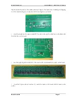
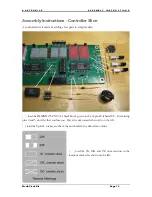
( ) load the 8 pin EEPROM 25LC1024 into the 8 pin socket, matching the pin 1 markings.
( ) load the 18 pin controller PIC16F648A int the 18 pin socket, matching the pin 1 markings.
The controller slice is done and ready to test.
Tests
The controller slice can be tested after building and before configuration, power it up and use the
menu buttons to advance to test. There are two tests, a segment test and an addressing test.
After configuring the clock and adding the jumpers, you can rerun the tests on all the displays.
Cases and mounting
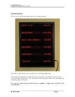
The boards can be mounted on a plaque in full view, or in shadow boxes or picture frames
behind glass or colored acrylic. Acrylic can be found at plastic supply stores.
Board locations
A clock must have one and only one controller slice and up to five display slices. The controller
slice can be in any position; on the top of the stack, on the bottom, or in the midst of the boards.
The boards will auto number themselves at power–up starting with the board below the
controller and continuing down where it wraps around to the top board, and stops at the
controller board.
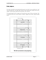
This auto-enumerate process can be watched by the address displayed at power-up. The inter-
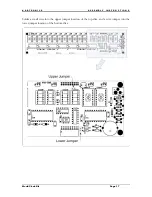
board signal needs to be configured using a pair of jumpers as described below.
Larger clocks
Clocks with more than 6 boards will require a larger power supply. Each board draws about 2/3
Amp which is 4 amps for 6 boards. The power is sent through the connectors using 4 pins for
each rail: ground and +5. Each pin is rated at 3 amps per pin so that is a limit of 36 total boards.
There may be a timing limit during the board enumeration, if you have problems feel free to email
for code modification to support large clocks.
My 6 slice version will reset if I turn on the selftest because it draws a bit over 6 amps with all the
test displays lit. The slices can be tested with smaller clock configurations. In normal operation
many characters on the display slices are blank, lowering the current draw below 6 amps and
allowing reliable operation.
Содержание World Clock
Страница 1: ...World Clock Operating and Assembly Manual...
Страница 32: ...KABtronics S C H E M A T I C World Clock Kit Page 32 Circuit Board Views...
Страница 33: ...KABtronics S C H E M A T I C World Clock Kit Page 33 Top Side Copper Bottom Side Copper Silk Screen Schematic...
Страница 34: ...KABtronics S C H E M A T I C World Clock Kit Page 34...
Страница 35: ...KABtronics S C H E M A T I C World Clock Kit Page 35...
Страница 36: ...KABtronics S C H E M A T I C World Clock Kit Page 36...
Страница 37: ...KABtronics S C H E M A T I C World Clock Kit Page 37...


