30
No existe ningún procedimiento para
averiguar la combinación desde la parte
delantera de la cerradura. Una combi-
nación perdida deberá anularse quitando la
cámara de combinación de la caja de la cer-
radura; luego se podrá colocar una nueva
combinación.
Nota: El procedimiento siguiente puede
utilizarse tanto para la cerradura interior
como exterior.
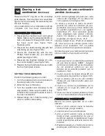
1. Quite la placa posterior de la cerradura
sacando los cuatro tornillos que van en
esa placa.
2. Levante la palanqueta (A) de la cámara
para sacarla del eje de control (B),
haciendo palanca con un destornillador
de cabeza plana (véase la ilustración 16-
1).
3. Quite el cojinete del eje (C).
4. Quite la cámara de combinación (D)
sacando los dos tornillos Phillips (E) que
hay en cada extremo de la cámara.
5. Quite la cubierta echada a un lado 3 del
compartimiento (A) de la cámara que
lleva la marca “KABA” (véase la ilus-
tración 16-2) golpeando suavemente con
un destornillador el borde de la cubierta
en el extremo del eje de control de la
cámara (A) (véase la ilustración 16-3)
para separarla de las juntas (B).
6. Ponga la cámara sobre un lado como se
ilustra en figura 16-4.
7. Mediante pinzas (u otra herramienta), quite
el aro “E” (B) del saliente de la placa de
desenganche (A) (ver figura 16-4),
después, levante suavemente el extremo
de la placa de desenganche (C) del
saliente (A).
Nota: La placa de desenganche (C) está
sometida a la tensión de un muelle y se
levantará fácilmente si se le empuja hacia la
izquierda para disminuir la tensión. Gire la
placa de desenganche (C) lo suficiente
como para liberar los engranajes (D), pero
no más allá de donde se indica en la figura
16-5.
8. Apriete en la varilla de cierre (E). Ahora,
los engranajes (D) pueden girar libre-
mente (ver figura 16-6).
Clearing a lost
combination
Anulacion de una
combinación perdida
16
There is no procedure for finding an
unknown combination from the front of the
lock. A lost combination must be cleared by
removing the combination chamber from the
lock housing, then a new combination can
be set.
Note:
The following procedures can be
used for both the inside and outside lock
assemblies.
1. Remove the back plate from the lock by
removing the four back plate screws.
2. Lift the chamber linkage (A) off of the con-
trol shaft (B) by prying up with a flat blade
screwdriver (see figure 16-1).
3. Remove the shaft bushing (C).
4. Remove the combination chamber (D) by
removing the two Phillips head screws
(E) at each end of the combination cham-
ber.
5. Remove the 3 sided chamber cover (A)
marked “KABA” (see figure 16-2) by gen-
tly tapping the lip of the chamber cover at
the control shaft end of the chamber (A)
(see figure 16-3) with a screwdriver to
detach it from the staked joints (B).
6. Lay the chamber down on its side as shown
in figure 16-4.
7. With tweezers, or other tool, slide the “E”
ring (B) off the unlocking slide stud (A)
(see figure 16-4), then gently lift the end
of the unlocking slide (C) over the unlock-
ing slide stud (A).
Note:
The unlocking slide (C) is under
spring tension and will be easier to lift if
pushed to the left to ease tension. Swing the
unlocking slide (C) sufficiently to clear the
gears (D), no further than shown in figure
16-5.
8. Depress the lockout slide (E). The gears
(D) are now free to rotate see figure 16-6.
9. Turn each gear (D) so that the gear
pockets (F) are aligned as in figure 16-6.
10.Return the unlocking slide (C) over the
unlocking slide stud (A) while making
certain the five toes (G) are engaged in
the five gear pockets (F). If necessary,
adjust each gear to make proper align-
ment between toes and gear slots (see
figures 16-6 & 16-7).
Содержание SIMPLEX EE1000 Series
Страница 23: ...Notes ...


