WinKey USB SMT Assembly and Operation Guide - Version 1.5 12/26/2017 Pg 17
Contents
WinKey SMT PCB Bill of Materials .................................................................................................. 1
Kit Assembly .................................................................................................................................... 2
Figure 1 – WKUSB PCB as shipped with kit ................................................................................ 2
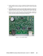
Figure 2 – J1, J6, and SP1 installed ............................................................................................ 3
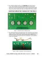
Figure 3 – Pushbutton switches installed correctly ...................................................................... 4
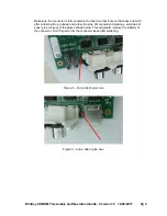
Figure 4 – Watch out !! Bent pin on RCA connector block .......................................................... 4
Figure 5 – Put a dab of glue here ................................................................................................ 5
Figure 6 – And a dab of glue here ............................................................................................... 5
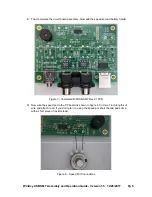
Figure 7 - Completed WKUSB-SMT Rev 01 PCB ....................................................................... 6
Figure 8 – Speed Pot Connections .............................................................................................. 6
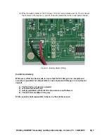
Figure 9 – Battery Holder Wiring.................................................................................................. 7
Customer Advisory .......................................................................................................................... 7
Kit Checkout .................................................................................................................................... 8
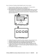
Figure 10 – Installation of battery pack ........................................................................................ 9
Figure 11 – Command button location ......................................................................................... 9
Precautions when connecting kit to a rig ....................................................................................... 10
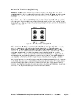
Figure 12 – Back Panel View of Output Ports ........................................................................... 10
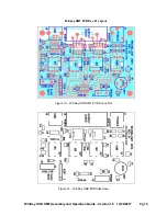
Figure 13 – WinKey USB SMT PCB Check Plot ....................................................................... 14
Figure 14 – WinKey USB PCB Silkscreen ................................................................................. 14
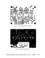
Figure 15 - WinKey SMT USB PCB Component Side ............................................................... 15
Figure 16 - WinKey USB PCB Solder Side ................................................................................ 15
Standalone Considerations ........................................................................................................... 16

