


Instruction Manual
Section Five
A.
If. CUTTER RUNOUT TOLERANCES
Periodically check the runout of straight arbors used to hold cutters. Do this
also for workhead spindles and their workholding adapters. Use a .0001 inch
dial indicator. If it shows more than .0005 inch runout at any point on the
workholding device, locate the source of the trouble before mounting the cutter.
Cutters usually run as true when mounted on a tool and cutter grinder as they
do in a milling machine. Only when the machinist has found the workholding
fixture tending to hold inaccurately, is it necessary to use a dial indicator to
check runout prior to grinding.
After sharpening, it is usually assumed that the final light cut has left the
cutter with no more runout than .0005 inch. However, in the case of carbide
multi-tooth cutters it is advisable to use a dial indicator to check the cutter
for no more runout than given in the table below:
III
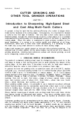
WHEN TO SHARPEN A CUTTER
Because of the many variables involved in mill
ing cutter usage, it is impossible to give exact
conditions of wear which will signal the time to
resharpen a cutter. The indicator used most
often is a visual check of the "wear land" (Fig
ure 19) which occurs just back of the cutting
edge on a milling cutter. Depending on the type
of cutter, material being machined, etc., the
wear allowed may be from a few thousandths to
1
/
16
inch Other methods of determining sharpen
ing frequency are: a predetermined time period,
depending on the number of production pieces machined; at a point where product
quality begins to be unacceptable from the standpoint of finish, dimension, etc.;
when an increase in power is required, noise generated, or heat occurs.
IV CUTTER INSPECTION AFTER SHARPENING
dial indicator
The main item to inspect on a cutter just
sharpened is the clearance angle just back of
cutting edges. Experienced machinists will
seldom have to check these angles, but there
may be conditions under which the clearance
tolerances demand actual measurement. This
is done with a hand operated clearance angle
gauge or by means of a dial indicator. The
following is a standard formula for the use of
a dial indicator to check the amount of drop
from cutting edge back of the end of a given
primary clearance or relief land (Figure 19A).
For each
1
/
16
inch width of land, each degree of clearance is approximately equivalent
to .001 inch on a dial indicator. For any width of land, the clearance C in degrees
= 57.32h/L, where h — indicator reading and L — width of land in inches.
— 3 5 -
Figure 19 A
Figure 19
Cutter
Diameter
Up to 12"
12" to 18"
Over 16"
Roughing Cuts
Cutting
Face
Periphery
and Chamfer
Cutting
Face
Finishing Cuts
Periphery
and Chamfer
.0015"
.002"
.0025"
.0005"
.00075"
.001"
.002"
.003"
.004"
.001"
.0015"
.002"
wear
land
cutter tooth
n=0.001 in. per degree
of clearance angle
when L=
1
/
16
Содержание B2000
Страница 14: ...Instruction Manual Section Three PHOTO 3 4 ...
Страница 24: ...Instruction Manual Section Four PHOTO 9 14 ...


